Another Sunday, another day in the shop
")
I got the other side of the valve chest gland profile rounded off, but here's what happens when you go a bit too far on the rounding table:
I should be able to take it out by filing.
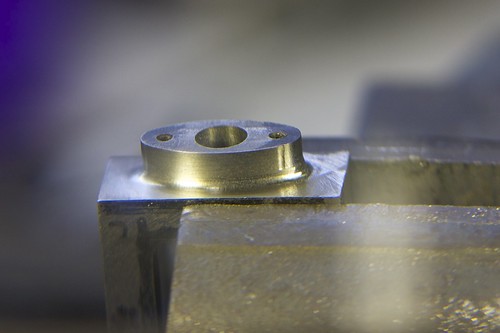
I milled the valve chest down to about the right thickness; the outer side is non-critical, and I left is slightly thick because otherwise I start running into the radii for the valve guide and the gland thingy.
Now the valve cover gets a cleanup, first with an old end mill of unknown sharpness, to get through the crust, and then with a nice sharp one on a finish pass:
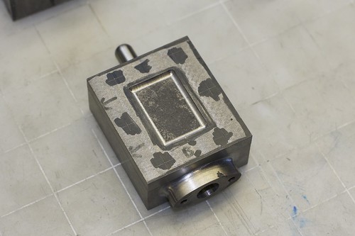
Then I did something that I might regret, which is to clean up the center indentation. Not having any ball-end mills, I used a little carbide burr that came with the Dremel:
It did the job OK, but I'll have to file away some of the machining marks. I'll need some riffler files to get into the concavity. I say I might regret it because it might make the cover look too too machined, and not like a casting. I guess it depends on how I paint it.
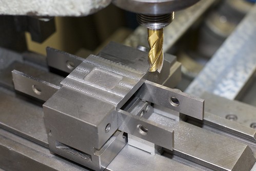
While marking out the valve cover for final size, I also marked out the stud holes:
It's another crazy setup!
I wanted to drill the cover, valve chest and piston all at the same time to ensure that all the stud holes lined up. So I came up with a setup, using the angle plate as a backing, a 1-2-3 block on each side between which the parts could be clamped, and some spacers at the back to align the top edges of the parts:
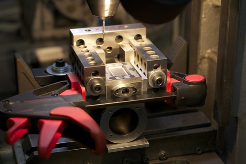
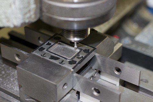
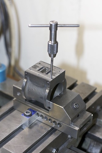
Some cardboard takes up the slight differences in thickness between the parts. I set this up so that, if need be, I could repeatably remove and replace the valve chest and cover to drill the piston itself. It turns out I didn't need to do that. One problem with this setup was that the holes are pretty deep, so the drill chuck could hit the 1-2-3 blocks. I had to use a full length drill bit (slightly undersize for the tapping size) to go all the way down into the piston. This worked fine, but I did manage to drill through into the exhaust hole. :-\ Oh well, that's not under pressure so it shouldn't be a problem.
The holes in the chest and cover were then opened up to clearance size (#27) with the part held in a screwless vise, held by hand. Then the holes in the piston were drilled to tapping size (#33), the 4BA taper tap started in the mill by hand, then tapping completed using a tap wrench.
Always a bit nerve-wracking on a part into which many hours have gone, but it went fine.
Now for a test fit:
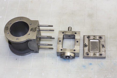
All the studs look straight, which is a good sign. And the valve chest and cover fit nicely over the studs, so my drilling in-place seems to have paid off.
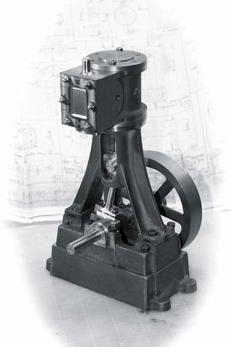
To end the day, some mock assembly pictures to see how everything fits together:
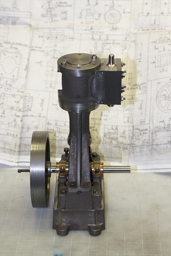
I have yet to drill the steam hole in the valve chest. I see some engines with steam and exhaust on one side (keep all the pipes together?), and some with steam in one side, exhaust the other. I'm not sure which I want yet.
Simon


