Brian builds Atkinson Engine

Home Model Engine Machinist Forum

Help Support Home Model Engine Machinist Forum:

This site may earn a commission from merchant affiliate links, including eBay, Amazon, and others.
I got up early this morning and tapped 6 holes in the cylinder plus drilling an 0.040" oiling port, and two tapped holes in the piston bosses. No disasters, no broken taps. all the machining on the cast iron is completed. Now for the BIG shop clean-up.
 
Okay---I'm going to solicit some advise here. How do I make this part? ---Or rather, the radiused portions thereof. Only the top radius is critical, as it must conform to the shape of the cylinder. The two on the sides are cosmetic. I know that I could set it up vertically in my mill vice with one side out past the jaws and use a boring head. My large boring bars are long enough to do this. The travel on my Z axis is only 2", but I could do it in two stages and lower the head the extra 9/16" for the second stage to cover the full 2 9/16" length of the block. I MIGHT be able to set it up on an angle plate attached to a faceplate and bore it in my lathe, but that would make for a pretty out of balance set up (I know I could add weight to the other side of the faceplate to balance it), but that makes for a lot of rather scary things whirling around in front of me while I do my boring trick. I could change the design, but that would be cheating. I have seen the trick where people make a boring bar with one end in the chuck, the other end supported in the tailstock, a toolbit in the center, and the part attached to the saddle---winding the saddle back and forth moves the part while the cutter stays fixed in place.--This does not appeal to me either, because there is no good way to attach the part to the saddle and I would have to make a special boring bar/tool. So----I'm open for suggestions!!!----Brian
CYLINDERSUPPORT.jpg
 
Brian,

I went back and looked at some pictures of your mill. I assume that the 2" to which you refer is the quill travel. I'd go ahead and mill the two inches, back off to your starting position, and lower the head so the quill can reach the bottom. Then I'd go ahead and mill the bottom part to match. The challenge with my boring head would be to match the bore diameter with a tool that is not calibrated in circle radius. Once I had it, I wouldn't change it for the bottom of the bore, just back the table off and then work your way in to a near match with the upper part.

The cosmetic side cuts are actually harder in this regard since they are visible and any mismatch will show. For them, I'd cut as close as I could the same way as above but then would use some emery paper on a dowel rod to work them down to a visual match.

Alan
 
If you can tolerate slightly elliptic sections instead of perfect circular arcs, then tilting the mill head (if that's possible) and traversing the table will do it. See my RADIUS program for the necessary computation.
 
Thats a great idea Marv---I'm just afraid that if I ever tilted the mill head I'd never get it back in tram again. I think of all options, the first one of setting the part up in my mill vice vertically then using the boring head is probably the safest/easyest way for me to go. In order not to have to start with a small radius and then adjust the boring tool radially a whole bunch of times I'm thinking that if I were to set the block up horizontally in my mill vice first and take a number of passes with my 1" dia milling cutter, then my 3/4" milling cutter, and then with my 3/8" milling cutter to hog out almost all of the material wouldn't be faster. Then I could set the peice up vertically in the mill vice, set my boring tool to the required finished radius and then plunge cut in one pass, return to zero position, lower the head, and then plunge the rest of the way. That should keep all the radiused areas consistent. What you think??
CYLINDERSUPPORTtest.jpg
 
Forest Addy over on home shop machinist suggested the following "Mount the workpiece to the faceplate Brian. No angle plate is needed. Your workpiece has enough stiffness to stand on its own. Drill the through holes first and use them for attachment to tapped holes in a thickish plate attached to the faceplate slots. The work can overlap the plate slightly to give space for the tool to run out into. Leave a little stock on the other work faces for fine-tuning dimensionally after boring. Your balance block can be set-up just inside the desired radius to bore the with the workpiece. You can then measure the cut dia and accurately determine from that the actual radius bored in the workpiece." ---I actually do like that--seems like a lot less work for me.
 
How If the shank on the boring bar is sufficiently long, can you extend it out from the head after the first half of the cut and then finish, or else use a longer boring bar?
 
To set a large radius what I do is pick up the edge of the part wit an edge finder then adjust away from part the size of your radius you want sat 1.5. Then load boring bar into spindle and adjust boring bar until it just touches part. Now you have the boring bar set for a 2.00 dia and a 1.0 radius. Then take and move table back into part ( go about .03 at a time. and bore then stop and move another amount continue until you get the radius you want.
 
Forest Addy's solution sounds good Brian. Look forward to the pics if you decide to go that way. Well look forward to the pics what ever way you decide.

Cheers
Steve
 
I agree the Forrest Addy solution sounds good. And cutting into the balance block and using that to measure the cut diameter is quite elegant.

--Tim
 
tvoght said:
I agree the Forrest Addy solution sounds good. And cutting into the balance block and using that to measure the cut diameter is quite elegant.

--Tim

Me too :D

Best Regards
Bob
 
I've been doing some more thinking about this solution Forest Addy came up with. Found a bit of scrap 3" x 1" aluminum bar x 8" long in my junk bin, and---Voila---
ASSYOFFACEPLATEANDPARTS-2.jpg

ASSYOFFACEPLATEANDPARTS.jpg

3INCHX1INCHBARX8INCHLONG-3.jpg

3INCHX1INCHBARX8INCHLONG.jpg

Of course this appeals to me because the only cost involved is a peice of scrap from my bin and a few bolts.---You will notice that I may have to turn the heads down a bit on a couple of the bolts which hold the part being turned, to get them out of the "cut-plain. The blue counterweight/gauge is made from steel and sized to exactly balance the weight of the aluminum part being turned.
 
Nice looking fixture Brian, should do the job.

Jan
 
Actually, since the 4 cosmetic holes through the part are called up as being 8 mm in diameter, I have decided to drill and ream them to 5/16" diameter. That way I can use four shoulder bolts to accurately position the parts, and I won't have to mill a register as shown on the green model. Also, the heads on 5/16" shoulder bolts are smaller in diameter and will not interfere with the cutting radius. The only milling on the face of the green fixture will be the counterbore in the center for boring tool run-out. The round register on the opposite side which locates into the center of the faceplate will be a seperate 1/4" peice which bolts on with a single flat head capscrew.
 
Well, there we have it---A new Lo-tech fixture, made completely from scrap, on my scaly, scary old faceplate. I included a rear side shot to show the center spigot attached to the back of the fixture which is a "precision" fit into the center hole of the faceplate. I had to cheat a bit on the "Counterweight" because I didn't have any 1" x 5/8" steel bar, but its going to be darn close for balance anyways and gives me something to measure to.
FACEPLATEANDFIXTURE002.jpg

FACEPLATEANDFIXTURE003.jpg
 
Just a little warning about faceplate work Brian.

Whenever you fit your faceplate, you should always check it out for running true, as because it is so large, even a tiny bit of something trapped behind it and your lathe backplate can give a rather large wobble at the outer edge.

In fact, I was always taught that a faceplate is disposable machine tooling, and should always be given a 1 or 2 thou skim just to make sure it is running perfectly true whenever it is fitted.


John
 
I just got back from a week at a rented cottage near North Bay, Ontario with goode wife and two grand daughters, age 4 and 8. Here is a pic of the 8 year old, Hannah, discovering "The Joy of Fishing"!! I see there have been a lot of changes while I was away. None of my pictures nor drawings were copyrighted, as I consider them all as "Public Domain". I do find it a bit disturbing that others who have emailed me privately feel that their copyrights have been infringed by the new owner of the website, and that they have been "permanently banned" for contesting this issue. I have been warned that there will be a "mass exodus" of the more experienced contributors to this website, and I have been invited to join new "Model Engineering" websites that will be springing up as a result of the way some of these issues have been handled. ----I feel that I personally haven't been harmed by this change of ownership, but I will take a "Wait and See" attitude for now. This has been an AMAZING site in the past for sharing of ideas, and civilized treatment of "new guys". I hope that the new changed ownership of the website doesn't hurt this forum, and that it continues to be a great site to "Hang Out" and share my builds.---and Damn---I want all my Karmas back!!!!!----Brian
HANNAHWITHFISH002.jpg
 
Last edited:
Brian
I'm with you on this, it has/is a great site for sharing ideas. Great learning experiences.
The reinstatement of the Karma system would be good
Regards
Ernie J ;)
 
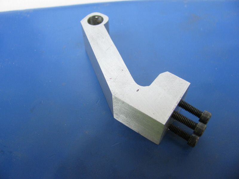
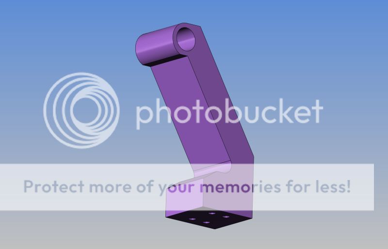
Hope you enjoyed your trip, and welcome back Brian

Austin (the new site administrator) has been fairly good at responding to our needs so far, and is working on coding up the karma system. He's still not said whether he can reinstate old karma. I am keeping a list of 'changes/missing features/etc' in the New Forum - New Problems thread in the About HMEM subforum.

The copyright 'battle' is becoming annoying. If those who have serious issue with it really had a problem with the possibility that someone else might steal their work, then it should not have been posted in the first place. Those who are upset that someone is "blatantly taking their work" are not understanding the TOS properly. Nobody can force you to give up your copyright without a written and signed contract. You still own your work. The only thing the questionable section of the TOS is allowing the new owners to do, is display the image/post/plans/whatever on the forums. EVERY major company has that same clause in their TOS, if they post anything from users. News websites that allow comments have that clause in their TOS. Facebook, MySpace, Google+, all have that clause. If they did not state exclusively in the TOS that they retain the right to "distribute" your content, you could sue them for simply putting it up on the forum that YOU submitted it to. If they tried to sell it, they'd be bankrupt from lawsuits in a heartbeat.

Nobody seems to understand that. I hope you do.

I'm not affiliated with the company who took over HMEM, of course. I'm simply a happy user of HMEM, who sees a chance for growth in this change. Some of the hiccups are a little frustrating, so I started the post to collect problems so that Austin can work at fixing them. Please don't hesitate to post any of your feature/function issues there.

I look forward to seeing the completion of your Atkinson, and many more future builds to come.

- Ryan
 
So, back into the machine shop after a week of swimming, fishing, and keeping up with grandkids.----Gee, its peacefull here today!!!! I finished up the block which is destined to become the cylinder base as far as I could go. It is milled to its final rectangular size, and the four .312 holes thru it are reamed. I can't do anymore with it until tomorrow when the stores are open and I can pick up my four 5/16" x 2 1/2" lg. shoulder bolts which will hold it to my face plate fixture. This morning I rooted thru my scrap bin and discovered a peice of 3/4" aluminum plate, so with a bit of CAD work on my model, the pivot support changed from its original thickness of 20mm to 3/4" (which is 19.05mm). There was nothing different nor spectacular about any of the milling, drilling, or threading that was done, so I'm just going to post a pic of the end result, along with the 3D model of the part.
PIVOTBASE001.jpg

PIVOTBASEMODEL.jpg
 
Back
Top