1/4 scale V8, first project.

Home Model Engine Machinist Forum

Help Support Home Model Engine Machinist Forum:

This site may earn a commission from merchant affiliate links, including eBay, Amazon, and others.
Hi Keith,
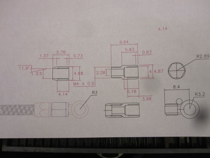
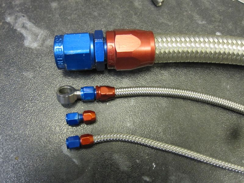
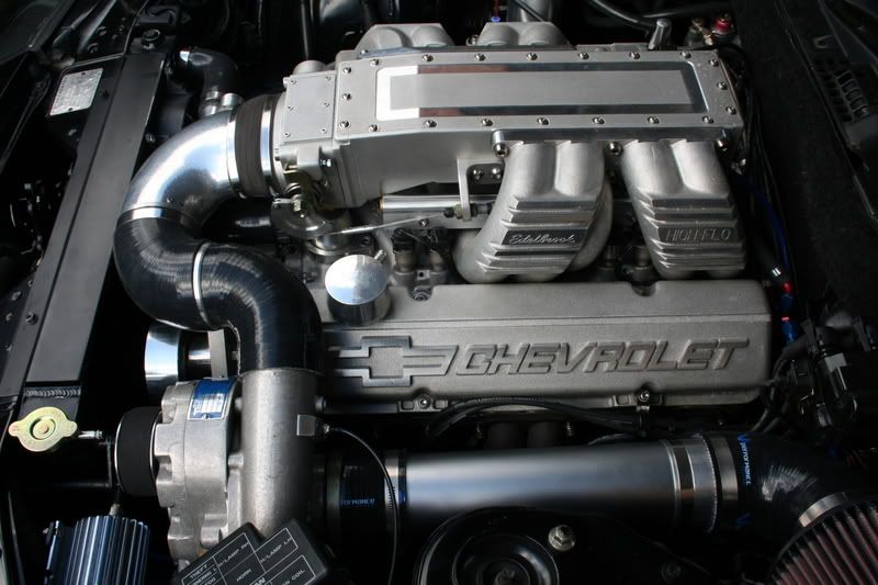
Incredible work on your engine. Your detailing is amazing. I really like those mini AN fittings. I sure could use something like that for the radial I'm building. Do you have a source for them or are they home made? Even if they're home made what are you using for the braided line?
gbritnell
 
Keith,

That engine is absolutely amazing, I cannot imagine in my wildest dreams that I could come anywhere near your skill.

Paul.
 
Thank you for your continued comments.

George, I made the AN fittings. the larger ones for the oil pump are made to seal on the tubing similar to the full sized ones, ie the conical bit on the fitting goes up the plastic bore, and the nut screws on to the outer braid to lock it on.

The tubing is 5mm o/d flexy pipe for cycle hydraulic brake lines. These lines come with a banjo fitting already on, but it's massive.

The smaller fitting is a bit different. The tubing is copper tube, 3/32" o/d. The end is swaged and the blue AN nut locks the swage onto whatever fitting it's going on. The braid is from the 5mm cycle line, with the inner plastic pulled out. The braid can then be stretched to reduce it's diameter from 5mm to nearly 3.5mm.
This slides over the copper tube, and the red AN nut locks the braid onto the copper.

The anodising is crap on the fittings and I've just realised that the ally I've been using is the free machining stuff.
I'll try some more with normal ally.

The red nut on the small fitting isn't long enough really, I think I've altered the drawing already.

I'll print some drawings off today and take a photo of them tonite if I get chance.

Cheers, Keith.
 
This is the drawing of the smaller fitting, which is a 1/4 scale version of a 6AN fitting, the usual size for a full sized fuel line.

002-5.jpg


003-1.jpg
 
Thanks so much for the drawing and picture.
gbritnell
 
Keith:

I think I'm missing something here. I understand how you're using the blue AN fitting as a compression nut to lock the flared end of the copper tube onto the male fitting, but I can't see how the red AN fitting is locking the braid over the copper tube. Is it just acting as a collar to cover the end of the braid? If not what am I missing, how does it lock the braid on the tube?

Confused in Iowa,
Don
 
I am wordless: your work, your attention to the details, the way that you solve problems, are astonishing :bow:.
If in any moment you want to do a CAD model, plans, analysis or a few renders realistic I think that I could help you with that.
I am working almost everyday with Rhinoceros, Bongo, Autodesk Inventor, Vray and Maxwell renders.
 
Sorry, just been on hols for a week.

Don, on the large AN fittings the lock nut squashes the liner and outer braid onto a tapered alloy inner, similar to full sized practice.
On the small ones, pictured above there wasn't room for this, so I went down the nut and flare route. When the nut has tightened down on the flare the braid is slid over.The red nut has to be slid over the braid first, then the braid is slid over the copper tube.
I initially accepted that it would just be a cosmetic collar, and that's fine with me, but when screwing the red nut on it does indeed lock the braid to the blue fitting.
It may be that the inevitable frayed ends of the braid get mangled up it the thread slightly and jam themselves into the joint.
Anyway, however it works it does seem to lock ok. I've not figured out how to get a fitting on the other end of the tube yet though!

Mosey, thanks for the Weber link.

Henry, thanks for the offer, I'll bear it in mind.

Cheers.
 
Blimey, doesn't time fly?
Some more pics and an update.
I've been finishing the liners and pistons etc. so the internals are just about done.
I then decided I had to have some inlet pipes similar to some full sized ones I had on my old Chevy motor.

Not really a job for a manual mill, but I thought I'd give it a go.

It's going ok so far........

nissanpics103.jpg


002-6.jpg


004-1.jpg


005-4.jpg


010-3.jpg
 
Just found this and can't believe what I am seeing! Absolutely incredible skill. :bow:
 
you took the words right out of my mouth Steve.
awesome, just awesome :bow: :bow:
Pete
 
Humina humina humina th_confused0052

OK....tell us about the passages.....please :bow:

Dave
 
OMG, this is really depressing. From now on I am going to collect butterflies instead. ;D

Jokes apart, that is really awesome. Please tell us how you did that.

Vince
 
That's pretty amazing Keith!

How do you keep track of the depths and step-overs for something like that?

How long does a piece like that take you?

A time lapse video of that being made would be so cool.

Awesome!!
 
wow_001.gif


That is nothing short of amazing.

Cheers :)

Don

 
You're all too kind.

Hope these drawings make some sense. I used a ball nosed cutter, and worked out the x,y and z measurements on the cad. The other variable was the dividing head angle. It started off veryslow but I soon got into the swing of it.
I reckon30 hours to make one set of pipes.
The other side will take about 20 hours at a guess.

About 15 sheets of drawings in total. I must be nuts!

009-6.jpg


011-7.jpg


010-5.jpg


To go with the inlet pipes I also need a new inlet manifold and plenum chamber.
I kicked myself first for all the wasted work on the existing ones, and then got on with it.

I try and use the dividing head wherever possible these days. It's ideal for these sort of jobs with odd angles allover the place......

015-3.jpg


016-5.jpg


017-4.jpg


018-6.jpg


019-2.jpg


005-5.jpg
 
Back
Top