A Small Vertical Steam Engine

Home Model Engine Machinist Forum

Help Support Home Model Engine Machinist Forum:

This site may earn a commission from merchant affiliate links, including eBay, Amazon, and others.
Thanks George, I will settle for standard.

Welcome aboard Vince :)

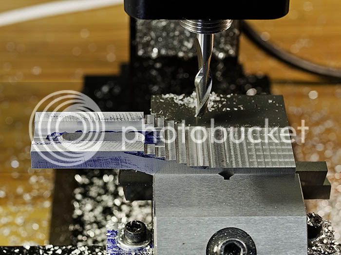
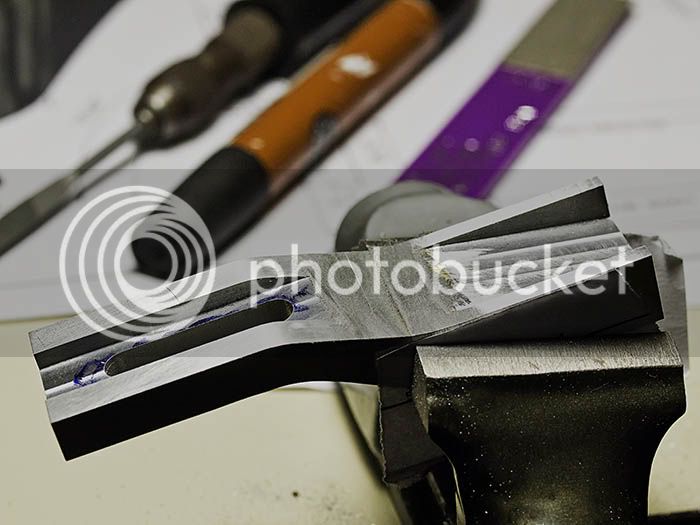
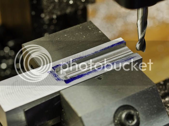
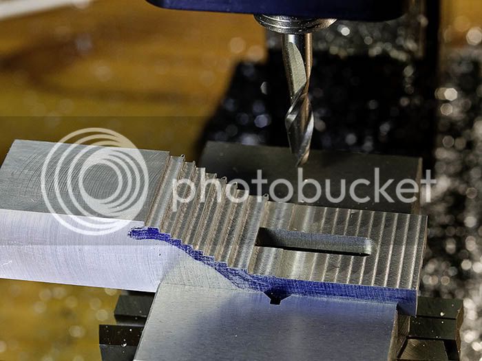
Had a good day in the workshop so have some pictures to share. A piece was cut from 25mm aluminium plate and squared up to the external dimensions using a flycutter. The part was milled to length and then shaping started. First operation was to mill the guide slot for the cross head. The cutter is 1/4" solid carbide designed for plastic but does a great job on aluminium. The cutter is made by Onsrud.

CrossHeadGuideSlot.jpg


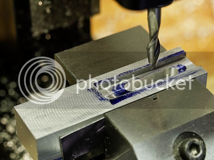
Next a slot was milled to clear the cross head boss.

CrossHeadClearance.jpg


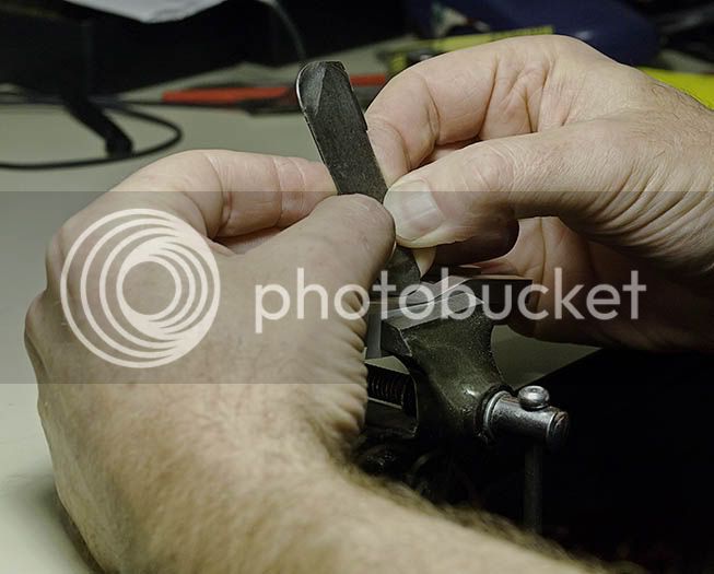
To ease the strain of milling on my little machine the excess waste was removed using a bandsaw. For aluminium of this thickness I use a 3 TPI wood blade.

BandsawWaste.jpg


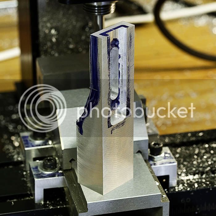
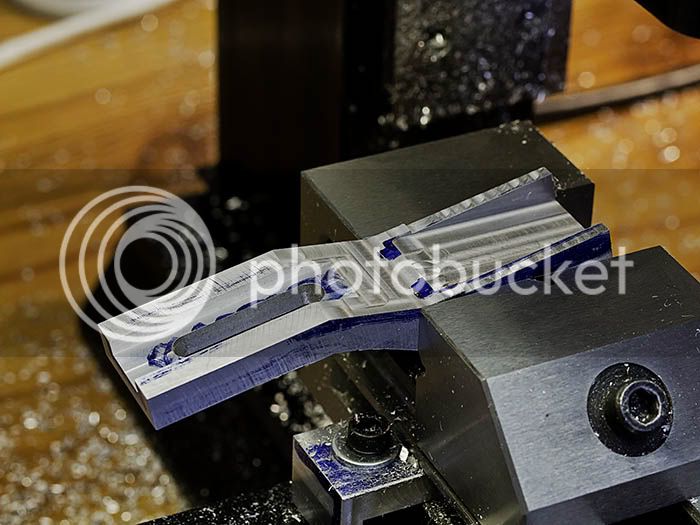
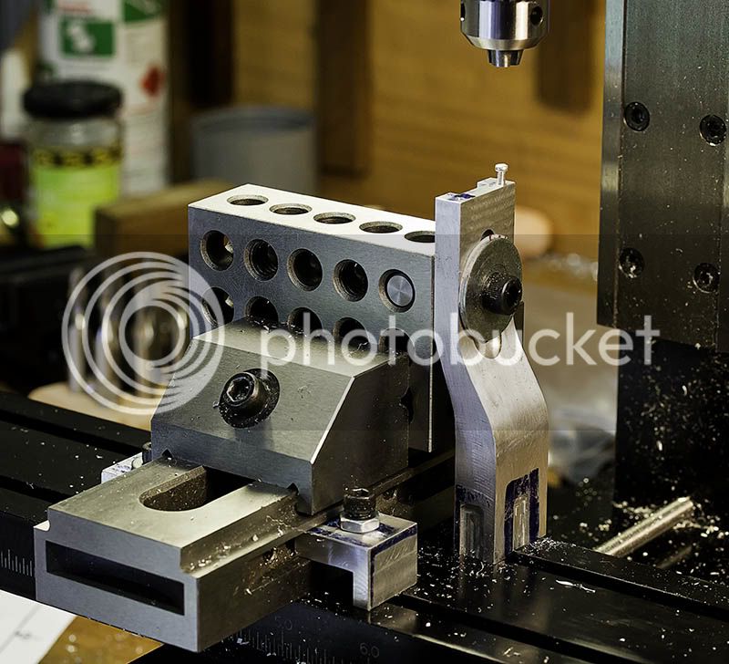
The rest of the material was milled away in steps followed by a few angled cuts.

StepMillBack.jpg


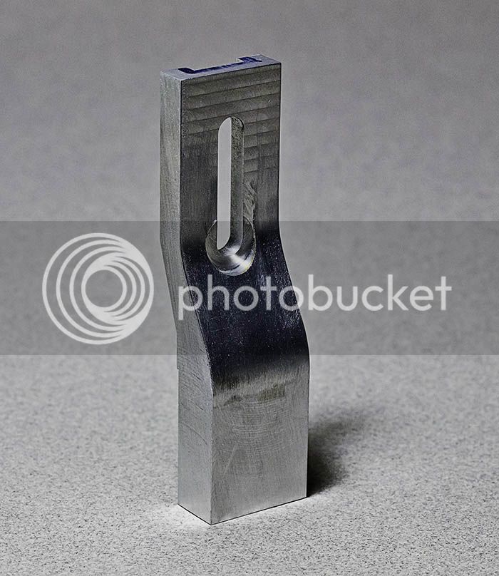
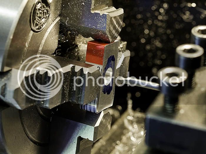
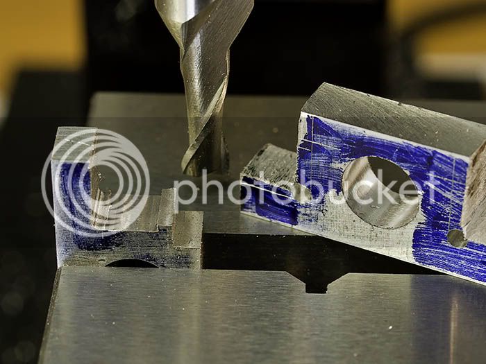
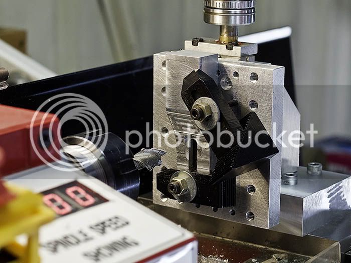
The cross head has a retaining washer that needs a 12mm diameter clearance milled, too big for the Sherline. The lathe was switched to mill mode, 45 minutes of setup for 3 minutes machining!

CrossHeadWasherClearance.jpg


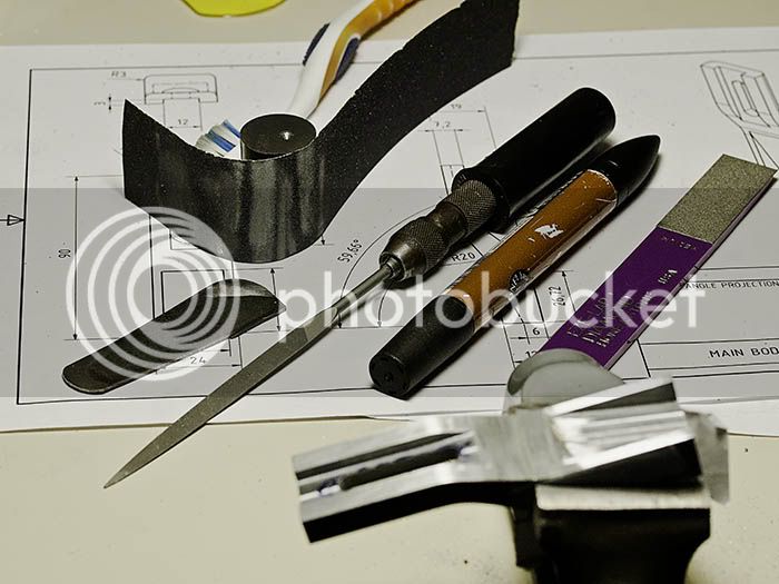
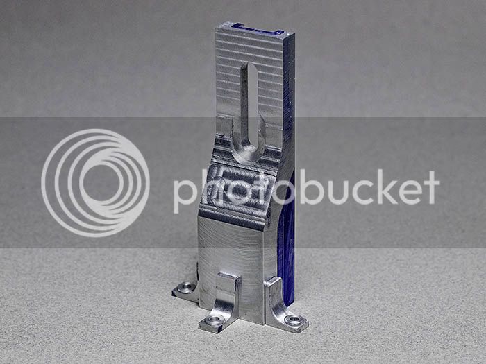
So that was the day gone but the part well begun. The final shot is a mock up with the parts to date. More tomorrow with a little luck.

MockUp1.jpg


Jan
 
Nice job so far Jan karma from me for the use of the bandsaw.

Don
 
Thanks Don. Aluminium works a lot like wood or plastic and in some cases these tools work better than the metalwork equivalents. I try to use aluminium for every part where it is strong enough because of its ease of working, especially if a lot of hand work is needed.

Jan
 
well my shop is more like 35c needs a bit of cooling
Tin
 
I have to admit I much prefer the cold to heat. Last summer we had two weeks of 37c + and nothing was done but what had to be.

Today's machining is much like yesterdays but on the other side.

MillStepsFront.jpg


A clearance was milled for the crankshaft.

CrankClearance.jpg


That was it for machining apart from a couple of holes to drill and tap when I can make my mind up where to put them. So it was time to start the interesting work of sculpting and blending. Convex surfaces are pretty easy to smooth and blend requiring only a file and some patience. Blending the concave radii is much more of a challenge. The lines left from the step milling provide a depth guide but also make the file want to drop into them. To get around that I made up a steel scraper of the right radius and scraped a lot of the material away. The scraper acts a bit like a shaper with a form tool which allows you to remove material from exactly where you want. It's a game of patience but good fun. Only got the back done and a lot more to do.

BlendedRear.jpg


That's it for today MotoGP on tonight so no more filing until tomorrow.

Jan

 
Jan

Can you please show the scraping tool that was used?

Vince
 
Thanks Dave, should get a bit more done tomorrow.

Vince I will post some pics tomorrow and a bit better explanation of how it and I work.

Jan
 
Wouldn't you find a rotary file great right now. I do love to shape metal, convex shapes are work, but a thing of beauty after you have shaped it. Looking good Jan.

Don
 
Take *that*, all you CNC guys. ;D I truly enjoy being witness to how complex shapes are arrived at using manual techniques and some rather ingenious methodology. Nicely done Jan, I'll be waiting with baited breath for the next thread installment. :eek:

BC1
Jim
 
hi Jan I'm looking forward to this billed good job dun so far
 
Thanks for looking in, your interest is encouraging, I suspected people might think I was plain crazy :big:

Describing the technique I use is a bit difficult and is still evolving but I will do my best. First a shot of the tools.

ToolsoftheTrade.jpg


The only item that might be unfamiliar is the piece of steel with rounded edges; that's the scraper. It is made from a segment cut from a wood handsaw and the steel is hard but still able to be filed. It is a wood workers tool but, as I mentioned before, I find a lot of wood techniques work on aluminium. The needle file has one rounded face and the bar end is used to curve the abrasive paper around. The diamond lap is used for sharpening the scraper.

So the problem we are trying to solve is to blend two flat faces into a curve that has been step machined. The area immediately next to the the curve edges is the most critical, attacking it with a file will most likely lead to a depression at the transition. The scraper is held by the finger tips and pushed along the edge of metal you want to remove. If the scraper is sharp and presented at the correct angle it will take a shaving, if not it will skate or produce dust. The correct angle is a bit of trial and error but tipping the top forward is good and sometimes twisting a bit helps. You can feel when it works. After a bit of scraping the surface is difficult to read as regards flatness so a bit of filing or abrasive consolidates the surface. Lots of marker pen is used to be able to see where the work is going on. This is detailed work and I like to sit down as it takes a while and also to use a jewellers loupe because you have to be able to see it if you want to work it. I hope that makes some sense but if not I will try some different words/pictures :)

Finally progress to date, the front has been a bit more difficult to work and the milling might be off a bit so it might not clean up! It is interesting to compare the shot of the machined part to the latest pic.

FrontProgress.jpg


Jan
 
Fearing that my explanation of scraper use was as clear as mud I have taken a picture of the tool in use. Hope it helps.

Scraping.jpg


Jan
 
Thanks Jan for the show and tell. For somebody like me who has never used a scraper it was informative.

Vince
 
Cool!
I've used one on wood, so why not metal........

Dave
 
The curves on my Seymour engine were all done buy hand while CNC is nice you can make smooth complex shapes without one. The file, scaper and abrasive paper are still useful tools.

seymour4.JPG

tin
 
It was quite possible for me to feed the model of the standard to VisualMill and then on to the CNC router, but that's work not my hobby. I value working by hand and the pleasant way it makes time pass. I guess I make engines to have something to machine and not machine to make an engine; I don't need the engine. It's all completely down to personal choice and I celebrate all of the choices ;D

Tin, the acrylic makes for an interesting looking engine, I should give it a go myself, maybe when I get tired of filing and scraping :big:
 
Herman Haeders book Handbook on the Steam Engine contains lots of useful pictures for the model maker. There are a few illustrations of the type of engine I am attempting and the first thing that I noticed is that the base of my version is too wide pushing the flywheel a long way from the main bearing. As a result the base has been narrowed on the Inventor model but the standard mounting feet limit how much it can be narrowed. Not wanting to discard the feet I decided to recess the feet into the standard by 1mm, this had the added benefit of making the feet look less "stuck on". The pockets was just a simple milling job with the standard held in the vice.

The only other machining job on the standard was to pop two M2 holes in the top to fix the cylinder support. I am happy with M2 fasteners but have acquired M1.6 to keep pushing the boundaries, one of my objectives for this project. The picture shows the setup for putting in the M2 holes and the pockets for the feet can be seen. With the Sherline there is not much space between the drill chuck and the table and you soon need to get creative to make a part fit even when it is only 90mm tall!

StandardM2Setup.jpg


The standard now needs filing and the feet stuck on before it gets a coat of paint. The next machining job will be the main bearings.

Jan
 
The bearing blocks are made in one piece but with separate bushes; making a split block would recquire M1 fasteners and I am not so brave yet. Started out by milling some 6mm aluminium plate to overall size and then boring 8mm dia. for the bush.

BearingBlockBoring.jpg


Next job was to drill a couple of 2mm holes to form the radius in the corners. Most of the waste was removed with the bandsaw and then milling started. The milling is not dimensionally critical as the whole thing will be filed and sanded later anyway. What is important is to remember to stay away from the corner radius and to leave on the material for the bead at the top. Nearly forgot about the radius and put a line in it but at least I didn't remove it completely.

BearingBlockMilling2.jpg


Not all that much to show for a weekend but it is going forwards at least ;D
 

Latest posts

Back
Top