A raw beginner attempts an Elmer's 25

Home Model Engine Machinist Forum

Help Support Home Model Engine Machinist Forum:

This site may earn a commission from merchant affiliate links, including eBay, Amazon, and others.
Just a quick model of the engine with a few little personal touches.
Hope you don't mind the post here on your thread. :)

01.jpg


02.jpg
 
Thanks Bob :)

That model is excellent ausdier, what software do you use?
I installed the trial version of Alibre but it was during a particularly busy few weeks so the trial expired before I had spent more than a few hours playing with it. But even that short time was enough to convince me that the learning curve is rather steep.
 
Thankyou clivel. :)

I currently use either Inventor Pro 2012 or Solidworks Premium 2011.
This was done in Inventor. (which I prefer)
Not wanting to hijack this thread but if you want to see some of my work look here http://grabcad.com/darren.simpson
 
Wow Darren, those are amazing :) :) thanks for adding the link.

It must have taken an enormous amount of perseverance to get to that level of expertise.

:bow:


Yesterday evening after work I hardened and tempered the boring tool. My wife was baking a steak pie for dinner, if she noticed the little tool being tempered in the corner of the oven while it cooked she never mentioned it :)

After finding that the tool performed satisfactorily on a scrap of steel, I touched it up on a hone before using it to bore the flywheel recess. I had decided on a deep recess so that it could be held to the shaft via a grub screw through the hub.

The flywheel was screwed to a scrap of wood with a 45 degree mitre. After starting the hole with a tiny centre drill it was drilled and tapping for a 3mm grub screw.

flywheeldrillgrubscrew.png


More by luck than design, the hole came out in the correct place rather than breaking out the back of the flywheel.

flywheelmounteda.png

 
This is progressing very nicely Clive and looking good. As you can see there is plenty of advice on offer if you get stuck, my only advice, given my newbie status, would be to read back through the threads on this site as there is a goldmine of valuable information just waiting to be soaked up. Incidentally I too am a fan of the diamond cutter it’s rather expensive compared to indexable tools but well worth it for it’s simplicity to sharpen and keep sharp, not to mention the good finish you can achieve. Keep at it I will be following.

Cheers Les
 
Nice work on the flywheel. It looks like the boring bar worked well.

I have used the oven for a number of "Off label" uses, but never while the wife was cooking in it. that takes it to a new level :)
 
'sneaking' a piece into the oven when old what's her name is preparing a meal ..........

The man has stones ...... nuff said. STONES i tell you.
;D


BC1
Jim
 
bearcar1 said:
'sneaking' a piece into the oven when old what's her name is preparing a meal ..........

The man has stones ...... nuff said. STONES i tell you.
;D


BC1
Jim

Yeah ...
and she keeps them in a bottle on the kitchen window sill :)
 
Rof}


At least you know there being stored safely and out of harms way ;D


BC1
Jim
 
Unfortunately life had conspired to keep me out of the workshop for a few days, resulting in no progress until today when work began on the cylinder.

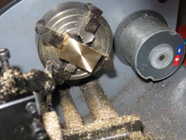
The plans called for a block of brass 1/2" x 5/8" x 1 1/8". Only having 5/8" square, I skimmed it to size in the 4 jaw chuck with the one pair of jaws reversed:
cylinderskimtosize.png


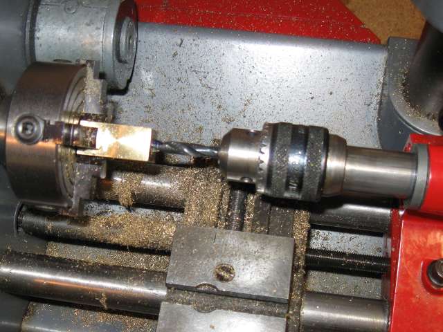
Next was drilling a hole large enough to get a boring bar in. Adjusting the 4 jaw chuck for centring the punch mark took ages, but the drilling itself took even longer, anything but the slowest feed of the drill would cause the lathe to jam and stall, even though I used a series of drills slowly increasing in size. I have read that one should smooth the cutting edge off the drill with a stone when drilling brass, but not being too sure what to smooth and only having one set of drills I skipped that step :)
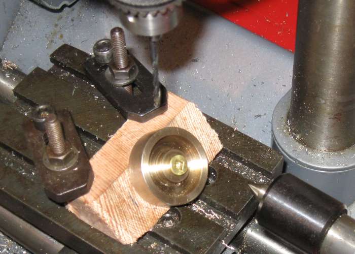
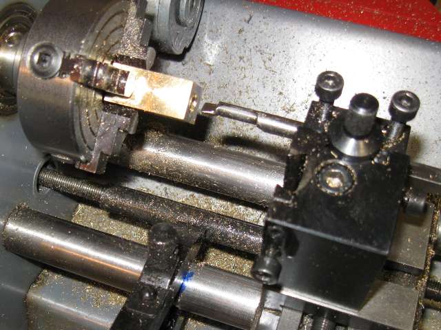
A bigger problem was judging how deep to drill to the correct depth. The tailstock dial was no use as I kept losing count of the number of turns, which turned out to be pointless anyway as the depth of the hole was slightly beyond the tailstock range. So in the end I put a dab of marking blue on the drill shaft and marked the depth on it - barely visible in the next picture.
cylinderdrilling.png


As soon as the hole was barely large enough to accommodate the boring bar, using a clamp as a saddle stop, I bored the hole to the correct size with the little home made boring tool. This went really well, once it reached a fraction of a millimetre under size, without moving the crossfeed, I traversed the saddle back and forth a number of times. After which the size was spot on, and the finish appears to be silky smooth. Not having a reamer, I am hoping that this finish will be good enough.
cylinderboring.png


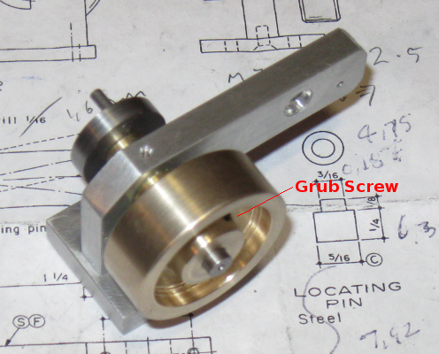
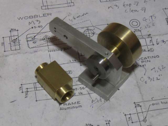
Although purely cosmetic, as per the plans I turned the open end of the cylinder into a tube, and then bevelled the edges of the square with a file. I thought it would look more balanced if the closed end of the cylinder was also tube shaped, so turned that round as well. I was really pleased with the way the completed cylinder turned out as seen here:

cylindercomplete.png


But then, holding the cylinder in position against the frame trying to picture the completed engine, my heart sank into my stomach .......
In my enthusiasm, I had turned away the flat part of the cylinder where the port should go :redface2:
so ... tomorrow I will have to remake the cylinder from scratch :(
 
One thing you could do is turn up a couple of rings maybe 3/4" dia and loctite/solder them to the ends. Mill the face flat and viola, someplace to drill the port and an interesting spool shaped cylinder. ;D

I just hate to scrap brass for any reason. :eek:

Nice work so far! Thm:

Cheers

Jeff
 
clivel said:
In my enthusiasm, I had turned away the flat part of the cylinder where the port should go :redface2:
so ... tomorrow I will have to remake the cylinder from scratch :(

Done that!

When you get the part roughed to the basic size, use a sharpie to mark where holes and surfaces will be. It helps me from getting confused. Keeps me straight as to where the front or back is, where holes go ECT.
 
I agree with Steve. Been there done that. Sharpies are your friend.
 
Clive,

Don't despair quite yet. There are a few options here. First, how much did you turn down on the sealed end? That will affect the plan of action.

The very first thing I would do is look at the geometry and consider if you can move the pivot point on the cylinder to accommodate a "new and improved" port location that aligns with the frame porting. No, you don't want the port coming through the cylinder wall partly down the piston at TDC, but nothing says you have to drill that port perpendicular to the pivot face to catch the top of the bore. If you decide to go this route, I would very carefully spot the port location with either a prick punch to catch a small center drill and/or use a 1/16 end mill to start the angled hole.

One complication is that you will also need to lengthen the connecting rod by the same amount that you move the pivot or the piston would not get anywhere near the end of the cylinder bore, greatly reducing the expansion ratio. As drawn the #25 has an ER of 17:1. Moving the pivot point .125 inches will drop that to 4.2:1. The piston will also protrude from the cylinder at BDC by the amount you move the cylinder block which may cause some binding near BDC. Simply extend the connecting rod by the same amount you move the pivot point to address this.

Moving the pivot point will affect the running balance of the engine as well, but I wouldn't worry. My limited experience has been that these little engines all shake a bit anyway.

You could also turn and solder on an oversized sleeve and mill it flat on one side as suggested, or all 4 if you choose. With this approach the port could then again be drilled perpendicularly to the port face. The new part could be made from bar or plate stock. The seam would become a fine accent line once you cleaned up the joined parts. If you turned off enough, you could also leave a gap between the added part and the main cylinder body, effectively creating one large cooling fin on the cylinder head. That might look interesting.

Were it not for the issues of running aluminum against aluminum, I would say make it out of a piece of aluminum and press it place for a different look.

No matter what, I would first carefully draw the proposed changes based on the geometry of your part, either with CAD or to an enlarged scale with paper and pencil and find the new dims and angles to help sort out a plan of action. If you want some assistance with that I am pleased to do so. I have the #25 drawn in CAD so it would a snap to revise my drawings accordingly.

At the very least, don't scrap the part you have. Set it aside for later. I am sure that you could design a new engine around it after a build or two.

Keep the faith!
Thayer
 
Hi Clive.
I agree with Jeff's idea, I think it goes something like this ?
Live and learn, we all learn by our mistakes. :)

Image.jpg
 
Thanks everyone for the words of encouragement and advice.
My initial thought was to scrap the cylinder and start again. But after all the good ideas here I am going to at least try to salvage it before going that route.

ProdEng thanks for the excellent link, I am definitely going to try that the next time I drill brass.

Jeff and Thayer thanks for the thoughtful ideas and the excellent illustration by ausdier. It will be a few days before I will be able to to get back into the workshop so I have plenty to mull over in my mind in the meanwhile.

And last but not least, thanks to Steve's and 90LX's advice I stocked up on some sharpies today. Hopefully they will save me from too many more self inflicted learning exercises in the future :)

 
One cool thing I noticed early on is that you can press a sharpie into the sherline spindle. I used this a few times during my early CNC days to do a rough layout on the stock and also check offsets were going in the right direction.

Thayer
 
ausdier said:
Hi Clive.
I agree with Jeff's idea, I think it goes something like this ?
Live and learn, we all learn by our mistakes. :)

Just like that, only I'd probably stop after step 2. ;D If you look at other Elmer V. engines he uses a lot of cyls with "rings" on the ends and square centers.

Cheers

Jeff
 

Latest posts

Back
Top