I stole a lathe!!!

Home Model Engine Machinist Forum

Help Support Home Model Engine Machinist Forum:

This site may earn a commission from merchant affiliate links, including eBay, Amazon, and others.
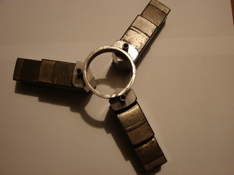
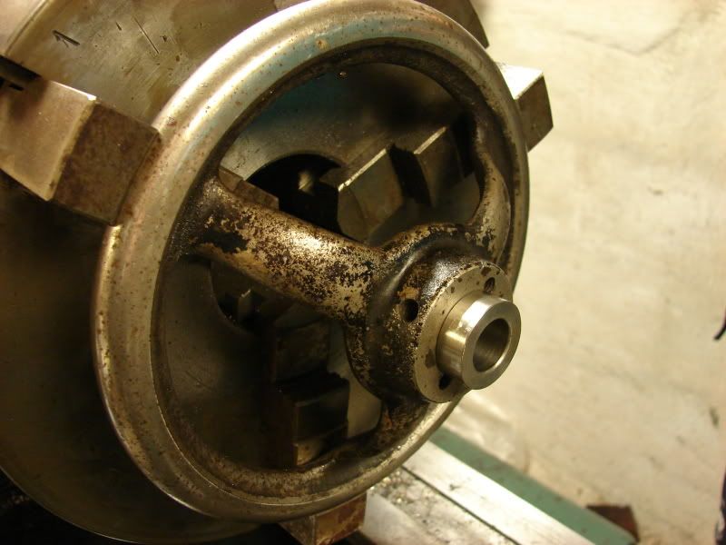
The handle on the tailstock is mounted. I turned a bush from some of the stainless i got with the lathe, then i turned the hole in the handle to fit the bush.

DSC03064.jpg


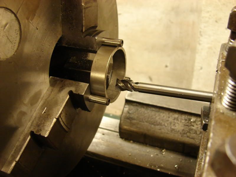
I don't have a boring bar yet, so i use a long 8mm carbide mill i got from work. the normal carbide mills are send to regrind, but this one was a ball nose mill, they don't regrind those. I just grounded the ball nose away, and grounded a cutting edge at the end of one of the flutes, it works really well.
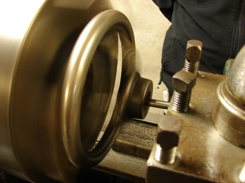
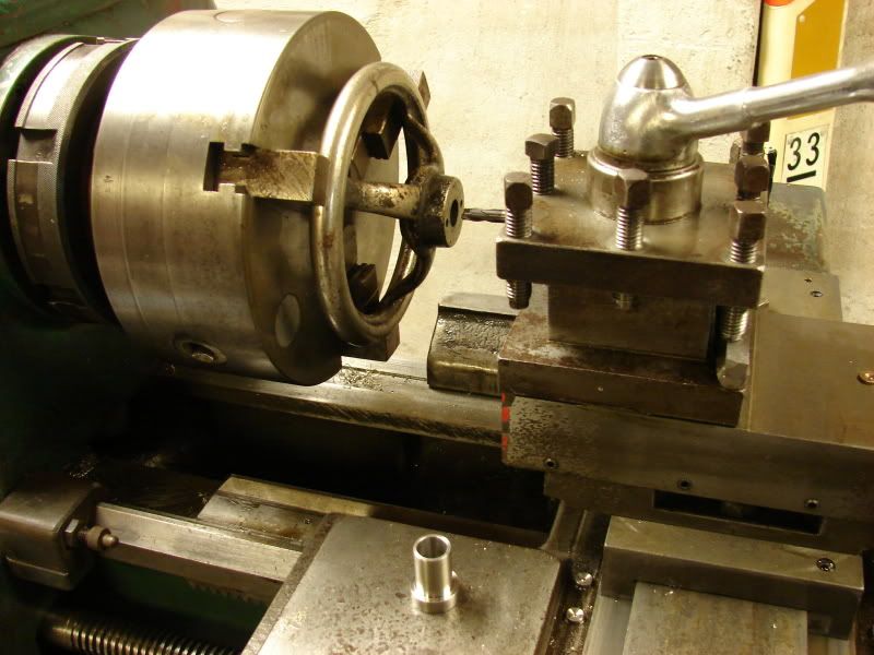
DSC03066.jpg


Bush mounted

DSC03067.jpg


Handle mounted on the spindle

DSC03068.jpg


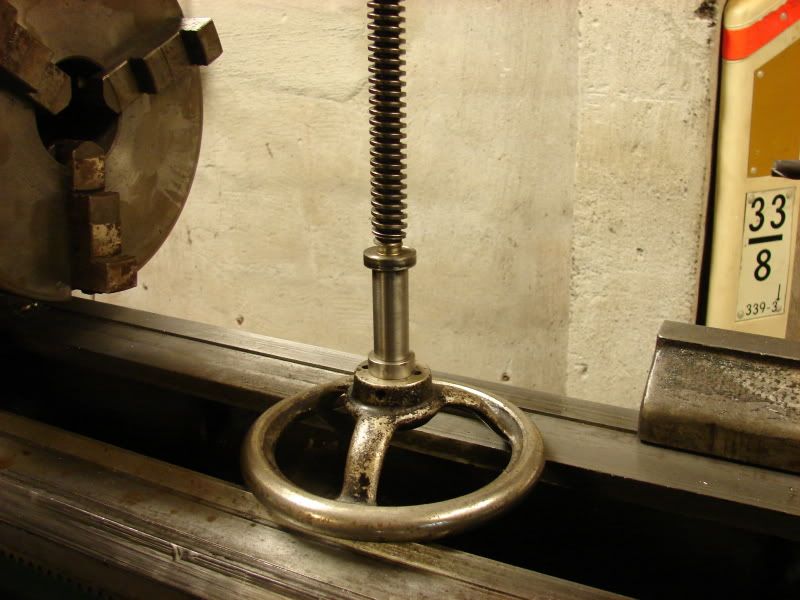
I just happened to have an old 1/4 UNC tap, the same size as the treated hole in the handle, so i drilled a hole in the bush, and cut treats in it.

Holt
 
Imperial machine converted to a metric screw but with the old dials?........ ???

 
The dial shown in the photo has 200 divisions so a 2mm or a 4mm pitch lead screw would make the dial make more sense if it is to be a metric machine.

Dan
 
Holt said:
Can anyone tell me the meaning with this scale on the cross slide, every ten divisions (from 0 to 10 etc) moves the cross slide 0.25 mm, reducing the diameter with 0,5 mm

DSC03063.jpg


It's the same on the compound, maybe i just have to mount the DRO in a hurry

Holt

Sure looks like an imperial dial on what sounds like a metric screw.

Robin
 
Dan Rowe said:
The dial shown in the photo has 200 divisions so a 2mm or a 4mm pitch lead screw would make the dial make more sense if it is to be a metric machine.
Dan

In order to make sense, it should actually be a 10mm pitch (or 1mm, but require a lot of turning) to fit the dial

Holt
 
I was thinking about what was easy to use, if the scale dosn't add up to the dia. of the workpiece, i could as well keep the existing wrong system instead of changing it for another wrong system

Holt
 
Put a dial indicator magnetic base on the carriage with the indicator set to read the distance of the cross slide moves as you turn the cross slide handle. You will quickly discover what the dial is marked for. When I'm doing precision work I always set up a dial indicator this way so it performs the same way a DRO would at a fraction of the cost. I was working as a machinist before anyone even thought up the concept of a DRO.
Holt said:
Can anyone tell me the meaning with this scale on the cross slide, every ten divisions (from 0 to 10 etc) moves the cross slide 0.25 mm, reducing the diameter with 0,5 mm

DSC03063.jpg


It's the same on the compound, maybe i just have to mount the DRO in a hurry

Holt
 
n4zou said:
I was working as a machinist before anyone even thought up the concept of a DRO.
I also know how it is to work without DRO. In my time as apprentice, 30+ years ago we didn't have DRO, neither the chemical plant nor the school had DRO on their machines, the two next places i worked at, had no DRO, then i got work at a small local toy company (LEGO ;D) they had DRO on all of their machines. Then i worked six years at a small company repairing their injection mould machines, we had a small stangko lathe and an old mill/drill without DRO, so i have done my share of reading scales ;)

Holt

PS: what should i do with my jaws, they are pretty worn, and have apparently been milled/grinded quite a few times. I was thinking of arc welding them with some hard material, and regrind them. I could also grind the slant part of them, to bring them closer, but the inner step get quite small this way. Any suggestions ?

DSC03087.jpg
 
If you are comfortable arc welding, then building them up with an appropriate alloy would definitely work, but obviously you need not only the welder, you'll need the ability to do some precision grinding.

Re: your cross slide screw and dial... Don't mean to sound like an annoying grade-school teacher, but are you SURE the slide is moving metric? The obvious way to really check would be to expose the screw threads and check their pitch with a ruler or compare with a thread gauge. You have the tails stock screw exposed, is it metric or imperial? I'd be amazed if just one screw is metric and the others are imperial. If they refitted the machine to metric leadscrews, they'd have done them all, I'd think.

Nice work!
 
Swede said:
If they refitted the machine to metric leadscrews, they'd have done them all, I'd think.

Unless someone stuck something in it to get the lathe going again with no care about the problems it would cause. I remember the owner of a machine shop I worked for went to an auction and purchased a lathe. When it got to the shop and put in operation it was found the cross slide ACME lead screw has been replaced with cheap all-thread you would find in a hardware store. They had run a tap through the ACME lead screw nut to match the all-thread so it would function when you turned the handle. The repair did not cost very much to get it right, it was the down time to make the repair that cost him. He had already contracted work for that lathe before we found that bastard repair.
 
Swede said:
Re: your cross slide screw and dial... Don't mean to sound like an annoying grade-school teacher, but are you SURE the slide is moving metric?
I have had my dial indicator mounted at the cross slide, it measures a bit over 10 mm total, at two full turns (exactly) the dial indicator moves 10,00mm (exactly) The compound moves twice the distance as the scale (double up on that also) The main handle doesn't have a scale, but i believe it moves a odd distance at each turn

Holt
 
Swede said:
If you are comfortable arc welding, then building them up with an appropriate alloy would definitely work, but obviously you need not only the welder, you'll need the ability to do some precision grinding.

In my youth, i took a certificate in arc welding, but haven't used it in many years, with some practice i should be able to refresh it (almost as riding a bike ;D) When working as a toolmaker, precision grinding is everyday work, i have access to this:

DSC01469.jpg


And this:

DSC01467.jpg


And this:

DSC02970.jpg


Said in other words: Grinding wont be a problem ;D The real precision grinding isn't done until the jaws are back in the lathe anyway, i have a small grinding spindle from the tacchella universal grinder, i could use for that.

Holt
 
Building up and regrinding the jaws... you've got the skills and the tools, GO for it! ;D Then post some pictures!
 
As i have written before, i wanted to weld and grind the jaws, because they were very worn. I was talking to my boss today, and it turned out that we had some tread for the tig-welder, that hardens when welding, and this afternoon, i took the jaws to work,and started the job. Unfortunately i forgot the camera, so you have to settle with some before, and after pics.

DSC03086.jpg


I started by milling some 6mm holes in the jaws, with a carbide mill

DSC03103.jpg


Then i welded and grinded them. I used the Okamoto grinder and sinus plane, shown in a previous post, to grind the tapered area. It turned up that there was some small holes in the welding, but i have to live with that :D

DSC03105.jpg


The holes are made for two reasons, now i can use them, to clamp a piece of pipe when grinding the jaws in the lathe, and later they can be used when clamping thin shims


DSC03100.jpg


DSC03101.jpg


Holt
 
I didn't get a grinder home for the weekend, so i had to bore the jaws, i used a long solid carbide mill, and it went very well, already at the second light cut, i noticed the cutter touched all 3 jaws :D I took some more cuts to widen the contact area, but the rest have to wait until i get a grinder

DSC03107.jpg


Holt
 
Back
Top