Kozo A3 in 1.5" scale

Home Model Engine Machinist Forum

Help Support Home Model Engine Machinist Forum:

This site may earn a commission from merchant affiliate links, including eBay, Amazon, and others.
Hi Kirk

Just caught up with your build, that certainly is a lot of painstaking work you have put in there, and it certainly is coming along well, further advanced than I expected. I can see what you mean now about needing a large mill to be able to tackle a project of this size. Looking forward to the video of it steaming down the track resplendent in its new livery.
How much more time do recon you have until that proud moment..

Les
 
My goal was to be in steam 2 years from start, so that would be November this year. I have slowed down a bit lately as other things take up time once the weather turns nicer. I don't have to everything done to steam up the first time. So the cab, boiler jacket, smokebox cover, sand dome, bell, light, handrails, and whistle are optional to run on the track. That said, I want to finish/install everything that would require a lot of disassembly to add.

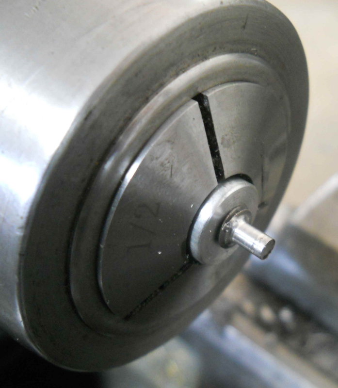
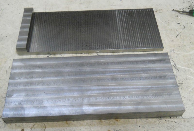
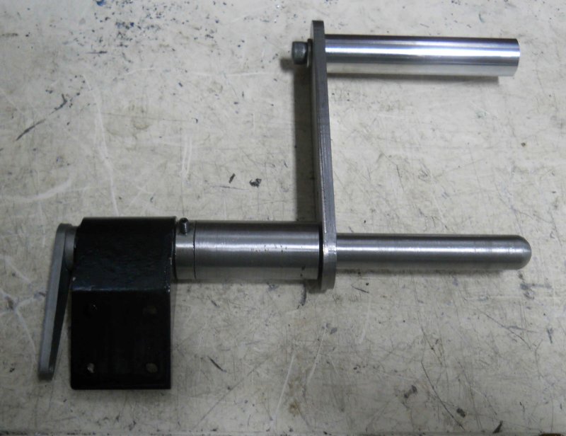
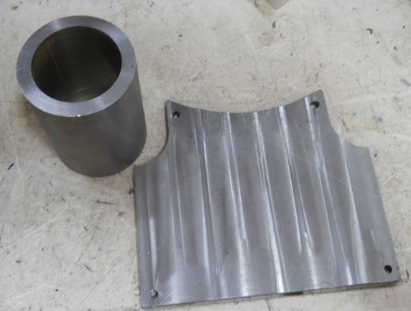
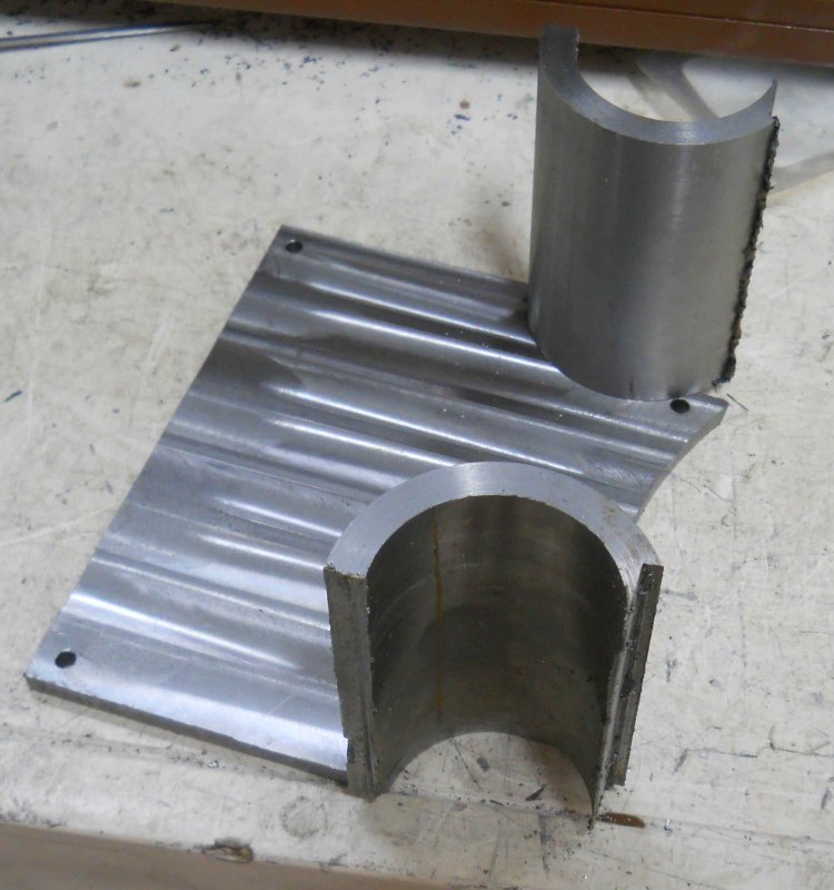
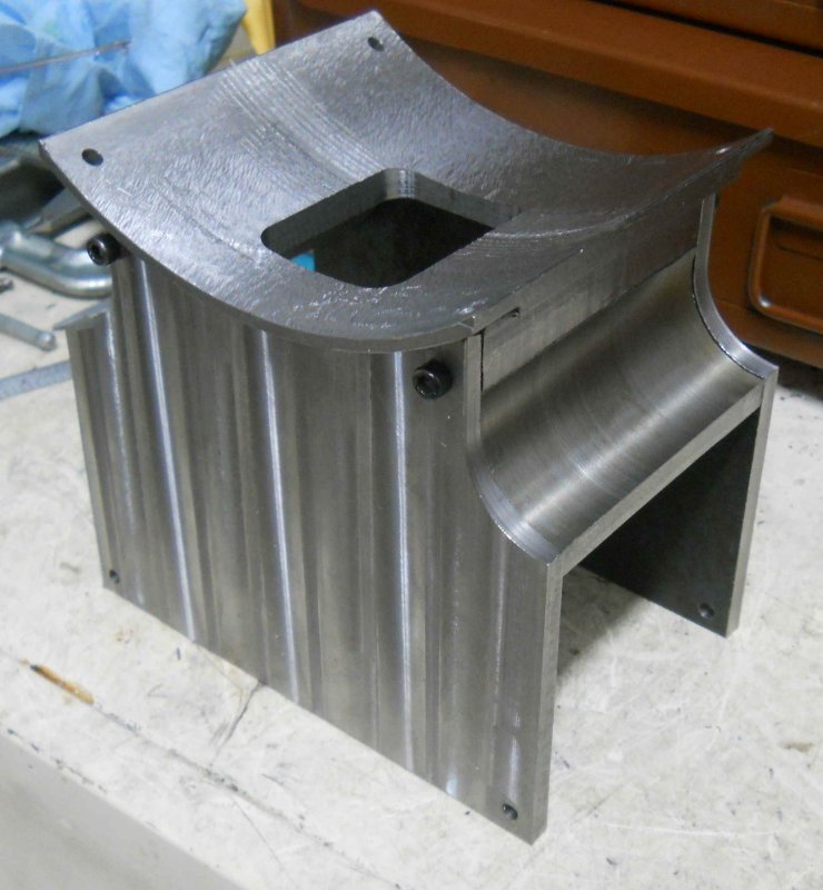
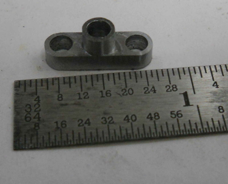
I got the 1/8" HRS for the bottom and front side of the ash pan. Milled them to size and MIG welded them together (if you call my booger welds "welding). Then attached the sides with JB weld. The second side is curing now. Once set I'll paint it and take a pic. This isn't a visible part so I can't say I took a lot of care making it look good. Given that the pan attaches to the boiler firebox support, removing it once the boiler is in place would be a bit of a PITA. Kozo's design would require removing the supports, so I made a small modification. First, I tapped the pin holes in the supports 1/4-20, and then bought a pair of hex head 1/4-20x1/2" bolts. Next I took a piece of 1/2" aluminum rod 1/2" long and drilled/tapped it on the lathe. After screwing the bolt into this jig, I was able to turn the end 1/4" of threads down to 1/8":
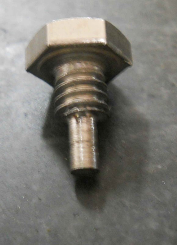
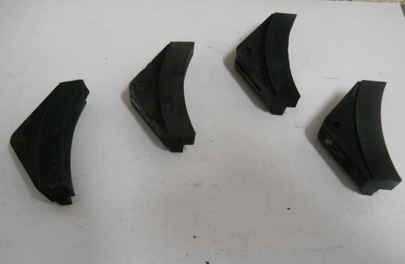
large.jpg


Here's the result:

large.jpg


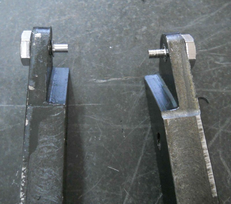
And installed in the supports:

large.jpg


If I need to remove the ash pan in the future, I can do so my removed the two screws and dropping the pan.

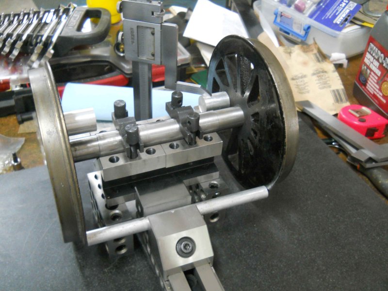
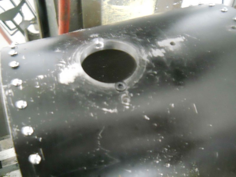
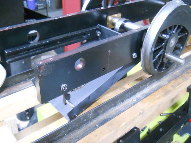
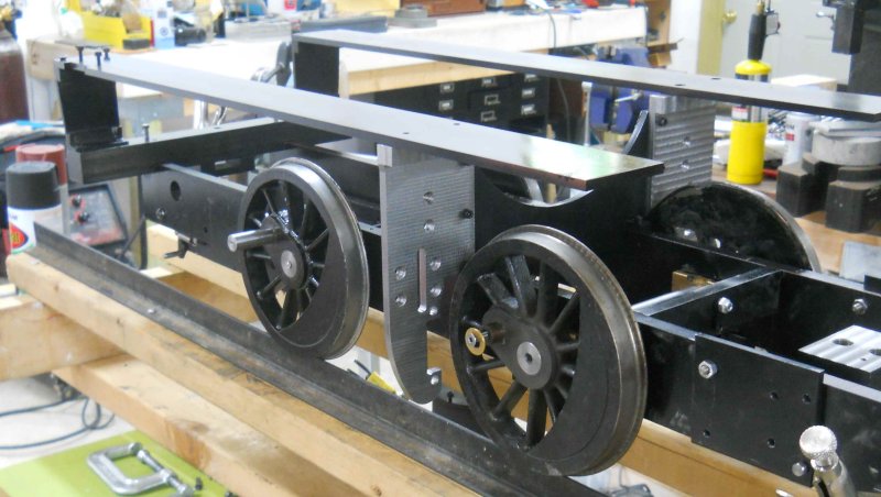
I started to reassemble the frame, and then to check the new quartering of the front axle. At that point I discovered I had quartered it backwards relative to the rear axle. Nothing to do but heat up on wheel, press it off, and redo the setup with the correct orientation. Compare this picture with the one show previously:

large.jpg


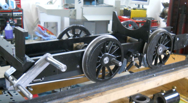
Now the right, horizontal, crank pin is rotated forward rather than back. Once it cures I'll mount to the frame and check it (with crossed fingers).
 
Some more work on the smokebox today: drilling holes for mounting the "accessories". The inner, countersunk holes are for the bolts to hold the petticoat, while the outer threaded holes are for mounting the base of the smokestack. Two lateral holes are for securing the base of the headlight.

large.jpg


The smokebox is now finished except for the holes for mounting the saddle.

I also painted and installed the ash pan on the frame:

large.jpg


And finally, my quartering seems fine as the side rods turn smoothly with the drivers, so the crank pins are now loctited in place.
 
A bit more progress over the past few days. I used some commercial blackening solution on the aluminum brake shoes, so these won't stand out so much once installed. It's a thin coating so scratches will show through. We'll see how well it holds up.

large.jpg


Then started work on remaking the guide yokes in steel, as I foresee some issues with the brass ones. Starting with some 4"x5/8" HRS bar, I machined two blanks after quite a lot of work. Then the first one was milled as shown.

large.jpg


I was experimenting with the concept of "high speed machining" on the CNC mill, where the idea is to take many passes with small engagement and higher feed rates. The job doesn't get done much faster, if at all, but it's easier on the tooling. Unfortunately when doing the same on the second piece the endmill moved in the R8 collet and cut too deep. Seems larger carbide EMs don't hold that well in R8 collets. I'll redo it using a HSS endmill, although that will be half as fast.

Next all the holes are drilled, and the slot for the radius rod cut.

large.jpg


I then screwed the work to a piece of aluminum in order to cut the profile. I also used a clamp for extra security. The final result:

large.jpg


The second one will be the same except being a mirror image.
 
Spent the day making the right side guide yoke:

large.jpg


Still need to drill and tap the mounting holes for the walk boards and mill a clearance slot for the rear wheel flanges.
 
Thanks for looking in, Steve.

In order to capture the "adjustments" I'd made to the brass yokes, I screwed the old and new together:

large.jpg


Then it was easy to mill the steel yokes until they matched the brass. Then I installed the yokes and tie plate plus the running boards on the rear supports. The mounting holes on top of the yokes were then marked with a transfer punch, drilled, and tapped.

large.jpg


The yokes are now painted and ready for installation when the time arrives.

Before any further reassembly, I wanted to get the brakes installed and checked out, since they need to go in from underneath the frame. So today I made the foot pedal. Kozo just specifies some 3/16" bar bent to shape, but I decided to make it in two pieces. If I want the part where the sole rests to be wider, it'll be easy to modify.

large.jpg
 
Finished work on the brake system and got it installed:

large.jpg


Rather than a screw for securing the removable foot pedal I turned a pin; seems simpler. I didn't offset the front lever arm as per the plans, but even so there's no interferene on the brake rod. If there were making the fork end's slot offset seems more precise than trying to bend the lever.
 
Another item that has to be built and installed before doing much else is the smokebox saddle. This piece is purely decorative as it does not support the smokebox and is needed to resemble the prototype. In the 3/4" version it's made from 1/8" brass and some copper sheet that can be bent to match the smokebox radius. Mine will be made from steel. The part that attaches to the smokebox is part CNC-machined and part manual. Here's the raw stock:
CRS 6"x4.25x1.

large.jpg


The smokebox mounting surface was CNCed as shown to match. I used a 5/8" diameter 4-flute HSS endmill with 2.25" flutes. Lots of chatter! It took over an hour of machine time to do half.

large.jpg


Some more CNC and manual work and I got this:

large.jpg


Front and back plates will be made from 1/4" CRS, and the sides of 16 gauge.
 
Next steps in fabricating the saddle:

After milling the central pocket for passage of the steam and exhaust, plus the 4 mounting holes, I mounted the saddle top and the smokebox on the tee. To ensure that the tee is in the runtime position I needed to remount the cylinders. Then I was able to position the saddle top and secure it to the smokebox with a clamp. The saddle is designed to be centered fore and aft on the cylinders.

large.jpg


Then I removed the smokebox with the saddle top still clamped to it, marked the mounting hole positions with a transfer punch, and drilled the smokebox. Show here mounted using 8-32 screws:

large.jpg


Now I was able to measure to determine the distance between the bottom of the smokebox and the top of the frame rails so that I could draw the saddle front and back plates in CAD. The goal is for the curve in the plates to end up flush with the frame top. To check, I used the Draftsight feature that allows printing a drawing actual size. I cut it out and was able to confirm the fit before cutting metal:

large.jpg
 
Excellent progress Kvom. Looking forward to seeing you loco unde it's own steam.
 
A little more progress after milling the front and back plates of the saddle. I clamped them in the mill vise to position the smokebox so that I could make the screw hole in the top.

large.jpg


Then drilled and tap the holes in the top and screwed the 3 pieces together:

large.jpg


Then a test fit with the boiler.

large.jpg


I still need to fab the sides and bottom, do a bit more fitting, and then paint.
 
Hi Kirk

Your build is coming along by leaps and bounds and looking really smooth, you are certainly doing some nice work here, I bet the CnC mill is a great help with some of those curved parts. This sure is a complex long haul compared to the little elmer and I don’t think I will be attempting to follow you on this one. More power to your elbow.

Les
 
A bit more smokebox progress made over the past few days:

Along with the boiler and smokebox tube I got a very nice and realistic smokebox door. It even has hinges and will open if the 10 dogs are unbolted around the rim. As with most of the engines at my club, mine will have the door attached to the front of the smokebox with 4 screws located at the cardinal positions. To make for more realism, I decided to add 16 more dummy bolts around the periphery. Here's the door frame with the dummy screws shown with the door itself. The screws are scaled 5-40 from Ameriican Model Engineering,

large.jpg


Since the screws are 1/4" long (shortest available from AME), they protrude through the frame's flange. This would keep the door from seating properly.

large.jpg


So I mounted the frame on the lathe as shown and trimmed the screws flush.

large.jpg


Here's the door reassembled and mounted to the smokebox.

large.jpg


Today I attached the problem of making the curved sides of the saddle. "We don't need no stinking slip roll', I said. I had a piece of thick wall DOM tube with a 1.5" ID. I cut a piece to length (3.125") and bored the ID to 1.686", which is the diameter of the curveed portion of the front and back plates.

large.jpg


I cut this in two pieces lengthwise using the mill, did a trial fit, and scribed the ends showing where to mill.

large.jpg


After lots of "whittling" on the mill I ended up with this:

large.jpg


I made the bottom cover out of a piece of HRS a few days ago, so with everything assembled it makes a pretty hefty saddle. The sides are just clamped in place right now. After one more trial fit of the saddle and smokebox on the chassis, I'll weld the pieces together and paint.
 
Today's progress was to work on the linkage between the lubricator and the eccentric. I purchased the lubricator from AME, and being a dual pump unit is larger than the Kozo design. A visual check of it mounted under the running board shows no interference with the main rod. The attachment to the eccentric is a tiny bracket that will be screwed to the outer trunion of the right expansion link. I made it to Kozo's dimensions as show on p. 226:

large.jpg


Rather than the flat, bent bar drawn by Kozo, I'll plan to use round bar with one end threaded for length adjustment. The lubricator's lever arm has 3/32 holes, so I'll need to use a 2-56 screw for the attachment, rather than an e-clip.
 
A very interesting build to follow and even though my interest is in very small things I have still learned a lot from your machine setups. Thanks for sharing.

Jan
 
I ran into a problem today. I had mounted the lubricator that I purchased from AME on the underside of the right running board to the rear of the yoke, as shown by Kozo. This is a fairly large unit and nearly as wide as the running board itself. The today I mounted my rebuilt reverse shaft, I discovered that the reach rod is blocked by the lubricator. In addition, the right reverse arm would be quite close to the lubricator output ports.

So it looks as if the lubricator will be mounted under the running board forward of the yoke, and I will use the motion of the valve rod to activate the lubricator's lever. The piping runs to the steam chests will be easier in that location too.
 
Our club is holding our Spring meet, so I saw a good number of beautiful steamers on Thursday. I also got some good advice when I took the chassis and boiler assembly out as well. I finally decided that the throttle will operate via a bell crank from the side of the steam dome. In principle the crank will operate on the left side, but since the dome is detachable, it can be rotated 180 degrees if it looks like the right will be better.

In any case, I want the valve itself to be in the center of the dome. The hole for the steam supply is located forward of center, so I designed the following setup:

large.jpg


I made the steel plate on the CNC mill, and threaded the central hole 1/8-27 NPT. The five smaller holes will attach the plate to the top of the boiler via 8-32 screws. Here it's shown in position:

large.jpg


The steam passage is a slot milled underneath:

large.jpg


I need to drill and tap the five mounting holes, and also a series of holes to admit steam into the dome.

I got another good idea from Fred V, who brought his new Sweet William loco. His boiler wrapper was made from a length of stove pipe, eliminating the need to roll sheet metal.
 
Drilled and tapped the holes for securing the valve mount, and also drilled two steam supply holes into the boiler. Since the valve passage is 1/4" diameter, I figure two 1/4" holes can meet the demand.

large.jpg


With the dome cannister in place:

large.jpg


As it sits, there is 1/2" of space between the top of the cannister and the top of the valve. I could mill off about 3/4" off the valve and the same off the cannister to make the dome shorter if need be. For now I'll leave it alone.

I still have to design a suitable bell crank assembly and throttle lever. The way the reach rod for the throttle will be positioned means I need to make sure it won't interfere with the turret or water gauge. The valve stem turns 90 degrees from full closed to full open, so a shorter crank means less travel needed for the throttle. I want to ask some other loco owners in the club how far their throttle levers move.
 
Back
Top