Elmer's Fancy II

Home Model Engine Machinist Forum

Help Support Home Model Engine Machinist Forum:

This site may earn a commission from merchant affiliate links, including eBay, Amazon, and others.

smfr

Project of the Month Winner!!!
Project of the Month Winner
Joined
Oct 29, 2011
Messages
287
Reaction score
2
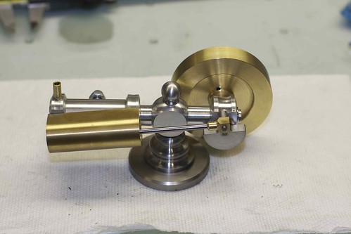
After mostly finishing my ball-turning tool (and finding out various things wrong with my "design" ;D), I was keen to put it to good use.

I've been eying Elmer's Fancy II, for which there are plans here: http://www.john-tom.com/ElmersEngines/18_fancy2.zip

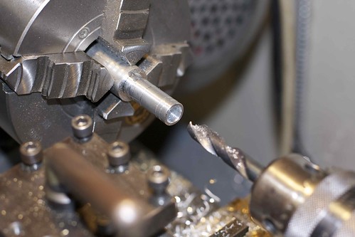
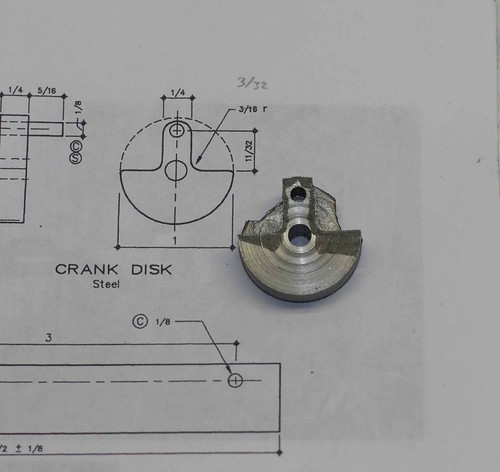
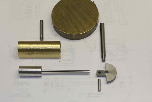
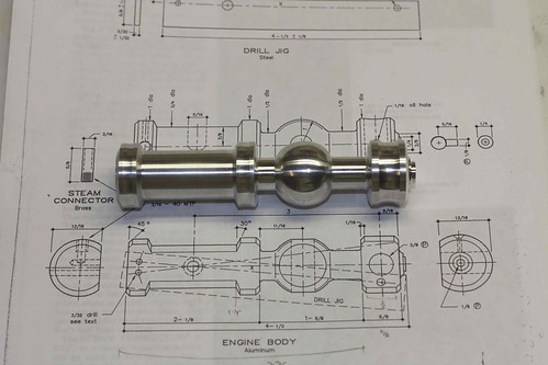
This is a nice little wobbler with some decorative touches, and will be my first scratch-built engine. So I pulled some Al bar from the stock bin, turned it down to just over an 1" in diameter, and marked it up for the body:


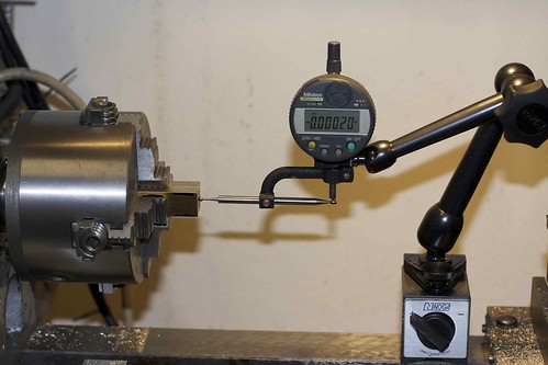
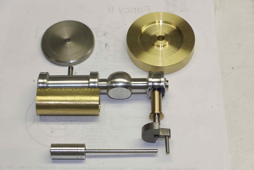
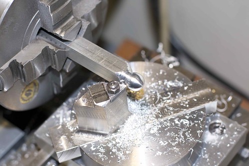
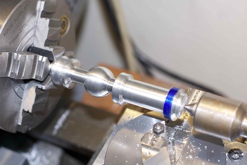
Then I went in with a profiling tool to get the major diameters close, and do the bevels, and with a parting tool to get the deep parts. Then I used my ball-turning attachment for the ball. Here it is after most of the turning:


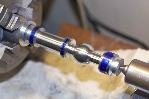
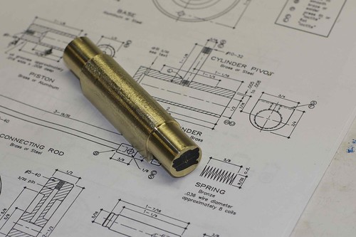
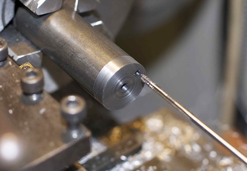
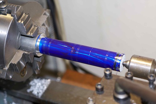
I decided to spruce it up a bit with a subtle concave profile in three places, not just the one in the plans. That forced me to cut it off and flip it around, because my ball-turner can't get close enough to the chuck:


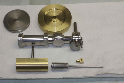
Final body after some polishing:


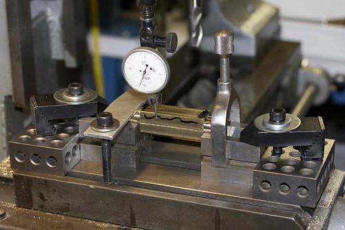
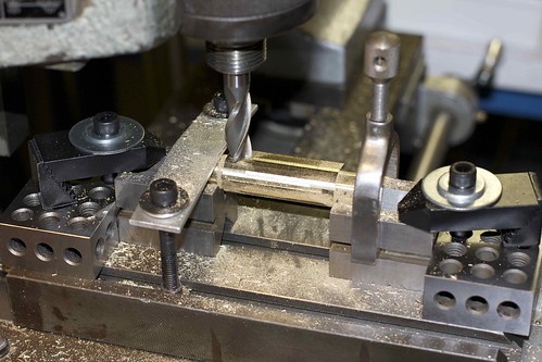
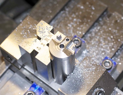
Next it gets attacked by an endmill to flatten one side. ;D
 
That's a really nice start on the column Simon :bow:

Looking forward to your progress Thm:

Kind regards, Arnold
 
Great start & great documentation as per usual - your postings are always informative.

Ken
 
Ball turner seems to be working well, one is on the list for me one day. It does look fancy. Good work as usual Simon.

Brock
 
A very nice column, and with the bonus of being made with some home made tooling.
looking forward to your progress.

peter
 
Brock: I need to follow up on the "Combined ball turner and rounding table" with the two biggest issues with my ball turner, but briefly they are:
1. Make sure you make it so that you can get close to the chuck. I lack enough clearance between the chuck and the cross-slide on my lathe, and didn't take this into account. Next time I'd resigned the base, and use a smaller diameter on the rotating part.
2. A smaller insert can get into tighter spaces. Don't leave any unnecessary material around the insert, because it just gets in the way.
 
Nice work Simon!! :bow:

Must be very satisfying to have such a piece on your workbench. Looking forward to see the engine coming along, I am sure it will be a beauty.

Regards Jeroen
 
I made a start on the cylinder today. First some 1" brass bar got milled down to to just over 3/4" (all the time thinking what a waste of metal that was, but I had no 3/4" on hand :( ). Actually, after milling one face down to 3/4", I quickly regretted it as it prevented me from doing some decorative bevels that I only though about too late. Oh well!

Not having a rotary table, I had to devise some way to get the curved cylinder profile that's on the plans. I decided to turn some extra material on the ends, then hold the work in two V-blocks. So I first marked out the location of the center of the rounding profile (which is not the same as the center of the bore!) on both ends, then centered in the 4-jaw on this punch mark:


I was pretty tickled to use a pretty new electronic Mitutoyo with the center-finding arm doodad from a really old dial indicator that I got at an estate sale ;D

Anyhoo, with both ends turned to the same diameter, I could then set things up with two V-blocks on the milling table, indicating to make sure things are lined up with the direction of travel:


Scribbles indicate the material to remove. Now I could rotate the work in increments, roughing out the profile:


and a bit of rough filing brings it to half-round:


The turned ends can now be removed, their job being done. Boring follows.

There are two aspect of the cylinder design that worry me, and they are visible on the plan in the above photo. First, see that cylinder pivot, that attaches to the cylinder via a #10-32 threaded hole? That hole is only about 3/16" deep, so I think it's going to be very unlikely that the pivot will end up aligned correctly.

The second aspect of this design that I don't like is that it looks like the pivot hole goes through to the bore, so the cylinder is going to be passing over this hole in the bore. Even if the hole doesn't get drilled through to the bore, it's going to be a really thin spot.

Anyone have any suggestions for improvement here? I guess the pivot could be turned with a disc on one end that screws to the cylinder body, or is soldered on?
 
Good going Simon Thm:

Soldering the pivot will work well. I used a little aluminium jig to keep things in place and square while soldering up on Elmer's Tiny. If you're interested, you can look here

Kind regards, Arnold
 
A few more bits and bobs done today. The cylinder is trimmed to size and bored. It ended up a little oversize. I had problems trying to remove material on the blind end of the cylinder bore, and stupidly tried to trim up that inside end with a 7/16" end mill, forgetting that the shank was 1/2", so the end mill promptly got wedged in the cylinder! After a lot of struggling, I eventually got the end mill out, but not without some damage to the bore finish, so I had to skim another few thousands off to clean it up. :(

How do folks get a flat bottom on a deep hole, other than with an end mill? With a boring bar less than half the diameter of the hole?

Anyway, the piston is turned to fit the cylinder so the bore size doesn't have to be exact. Since the cylinder is brass I'm using aluminum for the piston. Here's piston number 1 in progress.


It's a great fit to the cylinder, but I made two mistakes. First, I finished it to final size before it was parted off. I meant to leave it oversize, and skim it down once it was fixed on the piston rod.

Second, I misread the drawings, and made the 3/8" hole 15/16" deep rather than 11/16" deep, leaving no room for the reamed 1/8" that ensures that the piston is aligned with the piston rod. I blame the smudge on my drawings! So, I chucked up another bit of scrap Al and turned another piston.

I did all the drilling, boring and threading from the open end of the piston, which gets a bit tricky since you're working blind. I think it came out OK though.


The spacing of the oil grooves seems a bit odd, but that's what the plans suggest.

Next, the crank disk! Some 1" bar was cleaned up, and the center hole drilled and reamed. Then I offset it in the 4-jaw, using an indicator to gauge the offset, and drilled and reamed for the crank pin:


If I were doing this again I probably would have done this in a vice in the mill, since with that much offset in the 4-jaw, guaranteeing alignment with the center hole is dodgy.

I cut out the profile of the crank disk on the mill:


then did a rather butt-clenching parting off job. But the result was OK, and will clean up nicely:


Note that I think the 3/16" radius noted on the plans is incorrect; it should be a 3/32" radius to match the size of the central 3/16" hole.

I also made the various spindles and pins. This is starting to look like a bunch of parts for an engine!


The body on the milling table right now having the flat face cut on it. Maybe tomorrow I'll have some thing that I can turn over!

 
Very nice work. I like how you added a personal touch to your column. I used a router bit to round off the cylinder when on my Fancy II.
Alan
 
Various bits done today. I drilled and reamed the holes in the body for the cylinder pivot and the bearing pushing, while the body was still set up from milling the flats so the holes would be perpendicular to the face. I also drilled the cylinder for the pivot, and, as predicted, it was both impossible to avoid breaking through to the cylinder bore, and when I screw the pivot in, it's not square to the cylinder. I think I'll just try loctiting it in while things are held square; if I get the urge, I might remake the cylinder with some modifications.

Here is the current set of parts:


The bearing bushing was quite fun to make; a bit of messing around in the 4-jaw, since I made it from a cross-section of a large bronze rod. It's a nice push fit into the body.

The flywheel was a bit of a pain, as I don't have a tool that will do both sides of the recess, so I had to swap out cutters and mess around trying to get the depth of cut the same. What's a good kind of tool for that?

In the top left is the bottom of the base, from 303 stainless, faced up in the 4-jaw on both sides, then edge-finished by pressing against the chuck on a live center. Getting the chamfer involved some rather tight work with the topslide at 45degrees underneath the tailstock ram, but it turned out OK.

I think I'll start on the main part of the base next, so I can actually set things up. It's getting closer!
 
smfr,
Just use a radius tool sideways (full 180° radius) use it like a boring bar and plunge / work backwards and forwards.

Ken


I spent some time on the glass plate with wet & dry today, and cleaned up the cylinder, crank disk and the flats on the body. I rubbed the cylinder against the body with Brasso for a while to mate the surfaces nicely. I also made a brass fitting for the end of the connecting rod, threaded so that I can adjust the piston travel fairly easily.

Despite my best efforts, the piston isn't aligned to the piston/connecting rod very well. I'm not sure that it really matters on an engine of this type, but we'll see when things are assembled.

Looking at the parts now, I really think the cylinder needs some bevels on it to match the style of the body. If things end up running nicely, I might make another one.
 
Almost done! I now have the base mostly complete, after some turning and quite a bit of filing to get the profile of the base (I'm not super-happy with it, but it'll do, pig). I also drilled and reamed the hole in the body for the center post that holds the body the base, and made that center post.

Oddly the plans show the center post having a general diameter of 3/8", without any kind of lip so that the body is clamped down when you tighten the central screw. If I were doing this again, I'd make the decorative top in such a way that it was more than 3/8" diameter where it contacts the body.

Because I can, I made a spherical finial at the top of the center post:


You'll notice with my lame ball turner how far from the chuck I have to work, but it's Al so I was able to get away with it. The insert clamping screw is a bit temporary too; I was scared to thread deeper after breaking a couple of #6-32 taps in whatever mystery steel that holder is ;D

So, here it is, almost ready to go:


Still a bit of fit and finish to do, but I've tested it already, and it runs!
 
Engine looks great.
I feel your pain with the 6-32 taps. I've broken so many of them I will never use that size again.
Alan
 
Simon,

Despite my best efforts, the piston isn't aligned to the piston/connecting rod very well.

The normal method for doing these, when you have a solid rod with a piston on the end, is to make the piston slightly oversized on diameter, fit the two together, then hold the piston rod in the chuck and skim and lap the piston to fit the bore. Plus you could have put your oil grooves in at the same time.

Doing it that way ensures the rod and piston are always concentric to each other. It all depends on how accurate the runout is on your chuck, but usually you are within a couple of thou (0.05mm) at most, which is fine for an engine such as this. Or if you want it really spot on, just make a quickie split collet to hold onto the rod.

Looking very nice indeed.

I just love these uncomplicated barstock engines, purely because they can be shaped to give almost any look, as long as you stick to the critical dimensions, everything else is fair game, and they can be made by almost anyone, beginner or experienced alike


John
 
Hi John, thanks for the piston machining hints!

I did actually plan to do what you suggested this time around; leave the piston oversized, then skim once it was on the piston rod. However, the wobble on the piston was so great that there wasn't enough to skim off.

However, on this engine, the piston/rod assembly is a little ... odd. The piston is very long, with a deep pocket (presumably to reduce weight), then a 1/8" section (for alignment to the piston rod), then a bit of thread to match the thread on the end of the rod. There is no nut holding the piston to the rod. The rod is 1/8", threaded #10-32 on the end.

So the first issue I had was that you're working blind at the end of a deep pocket to do the 1/8" and threaded sections of the piston, after drilling a fairly deep hole (and possibly suffering a wandering drill). I drilled all the way through with a small drill first, then progressively widened out to 3/8" for about half the depth for the pocket. What I probably should have done is to only drill half way through first, widen up, then drill the last half from scratch to avoid drill wandering. I'm not sure that drill wondering was the real problem though, given this is Al.

The 1/8" section I reamed for a close fit to the piston rod, and I would assume that this section is long enough to ensure alignment, but apparently not (or something is off).

The piston rod has no clean shoulder at the ends of the threads, so tightening the rod in the piston just involves screwing it in until the partially-formed threads interfere. I think this is the source of the misalignment, and I've never had success getting accurate alignment with this kind of setup. I think a better design would be to have no threads on the piston, have the through-hole be 3/32", put a shoulder on the end of the piston rod, and hold the piston onto the rod with a recessed nut.


smfr said:
The piston rod has no clean shoulder at the ends of the threads, so tightening the rod in the piston just involves screwing it in until the partially-formed threads interfere. I think this is the source of the misalignment, and I've never had success getting accurate alignment with this kind of setup.

Agree - the thread is always going to pull up crooked.

I normally would have a shoulder on the rod and a reamed portion before the thread - the thread can't then pull anything out of alignment.

See photo worked fine - however given my recent experience with a drunken grained piece of CI that refused to drill straight - Bogstandard's method is always going to be safer.

Ken

dumpXX.JPG
 
smfr, die cut threads can go off a bit on a small rods (like 1/8"). On a small bore engine (like most of Elmer's) the tolerances are very critical, if you want a great running engine that will run on very low pressure.

Do all the machining operations and light polishing on your piston all in one step (set up) before cutting it off. On a reamer finished cylinder bore of say .5000, make your piston .4992- .4994. Eliminate the use of a threaded piston rod by drilling and reaming the piston 1/8". Cut your rod to length and polish if needed for a light press fit into the piston. Assemble the rod and piston with Loc-tite and your done. I have experimented with and without oil grooves on many identical engines. Their use doesn't make any difference. Use them if you like. I ran-in a few engines with Molly fortified oil and washed off the oil carrier. Afterwards they run fine with out adding oil. As a matter of fact, the addition of oil slows them down making it necessary to increase pressure to maintain the same rpm.

I've built a few engines using the above piston/rod method of keeping it simple.

-MB
 
Back
Top