Drawing projection woes

Home Model Engine Machinist Forum

Help Support Home Model Engine Machinist Forum:

This site may earn a commission from merchant affiliate links, including eBay, Amazon, and others.
Joined
Sep 6, 2007
Messages
1,275
Reaction score
322
Location
Skibbereen, West Cork
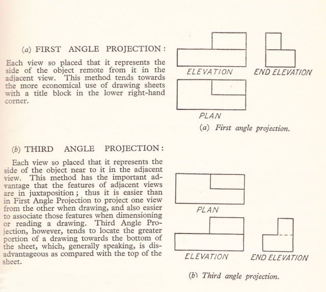
Most drawings these days seem to be drawn in the Third Angle Projection, whether stated or not.

I am machining a Stuart Turner centrifugal pump, the castings for which are quite old, or at least are no longer available. There was no information on the drawing sheet as to what the projection was, so naturally I assumed (deadly) that it was Third Angle.

Laid out the bolting circle and mounted up the cover plate on the rotary table to drill the 5 securing bolts, which were not of a symetric pattern. It was only when I had gone round with the centre drill and casually looked at the pump body that I realised that one hole was in the wrong place.

010kct.jpg


Some silver solder should hide the errant hole (the smaller one at 10 o'clock), which fortunately did not go all the way through.

Moral of this sad tale: Always make sure you realise which projection the drawings are in, particularly if they are of an older design and probably of British origin.

Dave
The Emerald Isle
 
Dave,

What a PITA :mad: but it seems readily fixable.

I'm old enough to remember that when I was first taught Technical Drawing it was all 1st angle projection.

Took me some time to come to grips with 3rd angle but when you think about it, IMHO it's a much more logical layout.

The use of 1st angle was supposedly to save paper in that a drawing was said to take up less space than with 3rd angle. Personally I can't quite figure that one, then again why should that be a surprise ;D

Best Regards
Bob
 
I worked for Milacron for a number of years. One of our lines of machines that I was the project engineer for was made in Spain and was all in 1st angle. So just about every day I got to play with both systems! :mad:

PITA!

It was like changing the breakers over every time at first...but I got good at it eventually.

Sorry about the cover!

Dave


UUUHH 1st angle, 3rd angle? I'm lost here. Would some one enlighten me?

I took a semester of drafting back in 83 but for the life of me I can't recall what this is.

Might save me a major goof up. ;D

Ron


Thanks Dave. Some really good stuff there.

I clearly need to bone up on my drafting knowledge.

Ron
 
steamer said:

I am still confused, The difference between the two types of drawings are how the object is layed out on the paper, is that correct? The views of the object look the same, just in a different order, so if this is correct what would it mater if you are looking at a 1st angle or 3rd angle drawing. I apologize in advance for my ignorance.
 
kd7fhg said:
I am still confused, The difference between the two types of drawings are how the object is layed out on the paper, is that correct? The views of the object look the same, just in a different order, so if this is correct what would it mater if you are looking at a 1st angle or 3rd angle drawing. I apologize in advance for my ignorance.

Put simply, reading a 3rd angle as a 1st will result in you making a mirror image of what you are trying to do. Not important in the example given on that page, but for more complex constructions .....
 
tel said:
Put simply, reading a 3rd angle as a 1st will result in you making a mirror image of what you are trying to do. Not important in the example given on that page, but for more complex constructions .....

I understand now, Thanks.
 
Is the plan view in the first angle projection the view one would see looking at the BOTTOM of the part?
 
Yes, Marv, that's it.

The correct hole is the one at 2 o'clock. Unfortunately, the bad hole was the first one I drilled, working anti-clockwise and it wasn't until I was on the last hole that I realised I had erred. The drawing of the cover had the hole pattern shown from the bottom instead of the (to me) more logical way of showing from the top.

Dave
The Emerald Isle
 
mklotz said:
Is the plan view in the first angle projection the view one would see looking at the BOTTOM of the part?

No, the plan view is still the top view.

I describe 1st angle as turning the part rather than the point of view. In third angle which most of us are familiar with, the part is "unfolded" to see the view you want. In first angle the part is rolled on the paper to see the view you want. The result is that the view looks the same on paper, but are swapped left and right. I hope that makes sense.
 
Your explanation makes perfect sense. The procedure makes no sense at all to me. What is the justification for it?

Are modern plans in the UK still drawn with first angle projection?

What's the standard for the EU?
 
mklotz said:
Your explanation makes perfect sense. The procedure makes no sense at all to me. What is the justification for it?

Are modern plans in the UK still drawn with first angle projection?

What's the standard for the EU?

Well, some years ago it was standard in Europe. It is still taught at the British Horological Institute.
Whether it is going to stay that way or change, I don't know.

Dave
 
First angle drawings - The part is dawn on the inside of a box sitting on the drawing board and unfolded flat.

3rd angle drawings - the part is drawn on the outside of a box sitting with the open side down on a table. The the box is opened and allowed to settle to the table.

First angle was used to draw cars that drive on the wrong side of the road, and 3rd angle is for cars driven on the right side...
 
Yes.............It's pretty confusing :-\

I hope the below pictures will remove some of the mystery.

Explanation of 1st and 3rd angle projections.

1stAng.jpg


Where 1st and 3rd angles come from and showing 1st angle projection

ang.jpg


3rd angle projection.

3rdAng.jpg


My way of understanding it is............ 1st angle views are pushed through the object and 3rd angle views are bounced back from the object

As a starting point, using the 3 standard projections............... if the plan is on the bottom it's 1st angle, if the plan is on the top it's 3rd angle.

This is NOT always true but more often than not it's a pretty good clue, especially pre cad drawings.

I hope this helps to keep you on the right, (i.e. left) side of the drawing ;D

Best Regards
Bob

 
My way of understanding it is............ 1st angle views are pushed through the object and 3rd angle views are bounced back from the object

Pretty much sums it up - personally I find the 3rd angle the more intuitive of the two.
 
So if youare looking at the 3 spot on a dice it's
AAAAA037.jpg

Ha! no wonder i prefer to work with B.O.E. (back-o-the-envolope) sketches!
In the UK, industry moved over to 3rd angle years ago, but the model engineering world still seems to favour 1st.
Even the drawings i've seen that Anthony Mount produce (and these are some of the clearest -none of that nonsense of beeing printed on dirty great big sheets that are impossible to keep clean in the workshop - all on handy A4 sheets) are in first angle, but at least they are clearly labelled as such.
 
I'm thinking back 20 years to my Heald days and I'm starting to get a twitch!.... ;D


I hated working on those prints!

Dave
 
peatoluser,

Your 1st angle is correct

Your 3rd angle is amiss you pushed through the 2 spot instead of bouncing back the 5 spot i.e the 2 should be a 5.

Hope this helps

Best Regards
Bob
 

Latest posts

Back
Top