Hi
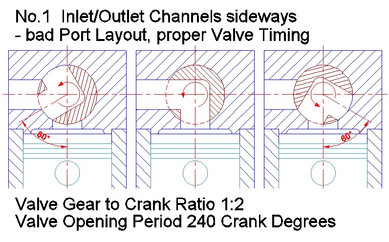
A rotary valve with inlet and outlet channels coming from the cylinder heads side will not work very well. You will get overlapping port edges, in any cases if you want to achieve a suitable timing for an IC engine.
I think some pictures will say more than a long explanation
..
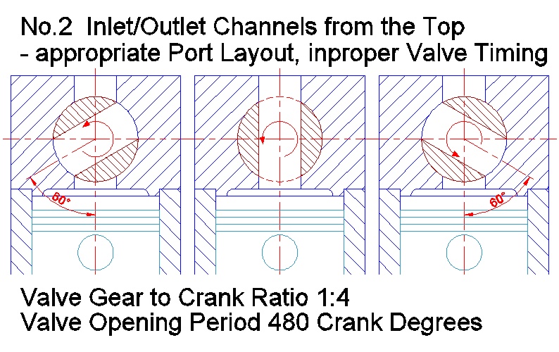
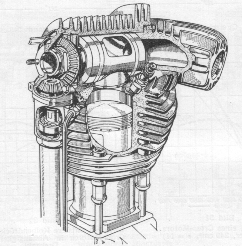
In the early days of engine construction Alfred Baer for example had the idea of arranging the channels upright from the top of the cylinder head.
But now the bore in the rotary drum will open the port twice at each rotation. So in this case the gear ratio has to be 1:4 in relation to the crankshaft. A new problem turns up, if you want a proper channel cross section the timing gets sick, this 120deg on the rotary drum means 480 crank degrees, that wont work.
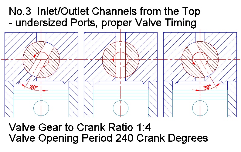
For that reason the Baer engine has channels in the shape of slotted holes instead of cylinders, so the front view section is much more slender and we will get the desired valve timing, but the cross section wont get really opulent anyway.
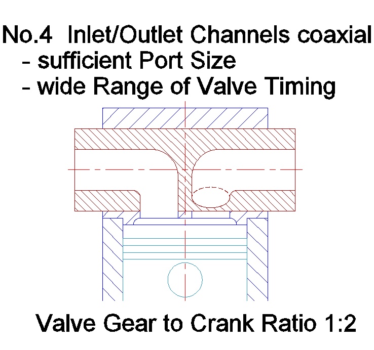
One good and practicable way is the coaxial design like the Cross Rotary principle, in- and outlet is coming from the front and end of the rotary drum.
This allows a wide range of timing layout and you can achieve sufficient channel and port sizes (in any case you dont want to build a high performance engine).
For increasing the port size further more you have to stretch the port openings from the cylinder side to the centre of the head. And that leads to a single port for in- and outlet duty, like the design of E. Brown you can see in this picture:
But this Brown rotary drum is a complex piece of craftsmanship, both internal channels open out into bended shapes to achieve the desired overlapping in the middle section without too much restrictions.
Achim


")