Encabulator build

Home Model Engine Machinist Forum

Help Support Home Model Engine Machinist Forum:

This site may earn a commission from merchant affiliate links, including eBay, Amazon, and others.
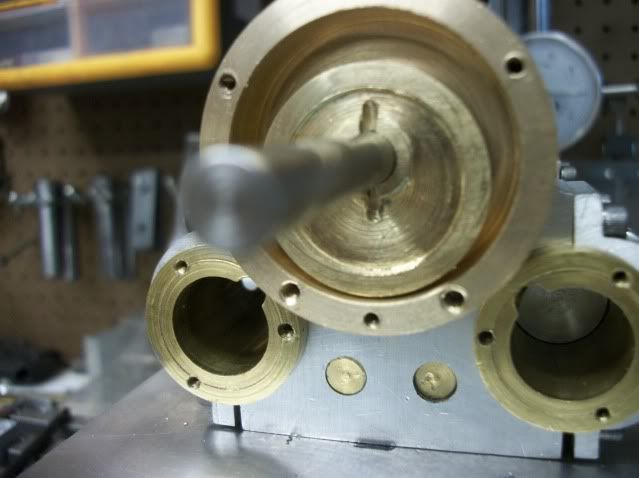
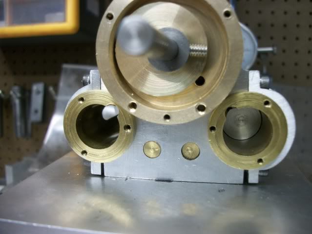
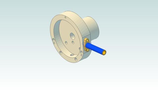
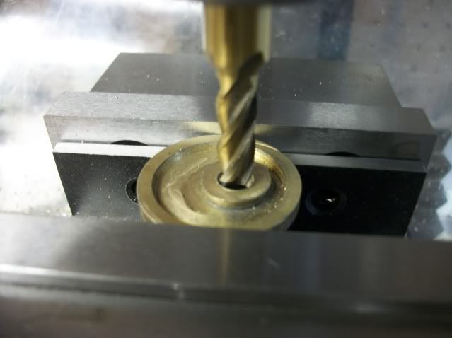
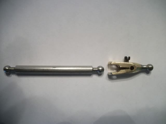
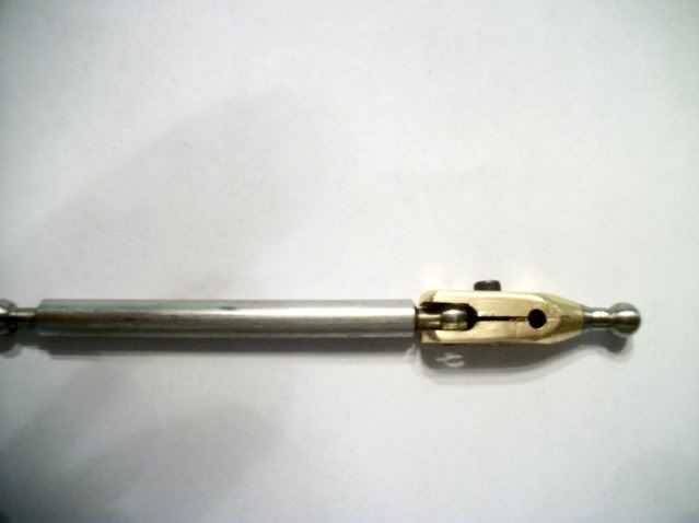
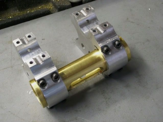
This post is going to be about ball joints (again). I know I have posted on that subject before but every time I revisit the subject something new (to me) is discovered. In the first pic below, are two pistons attached to the dingle arm with ball joints. On the right is a nice looking design proved less than reliable. On the left is the new design that seems much more reliable. Time will tell.

marleytowel002-1.jpg


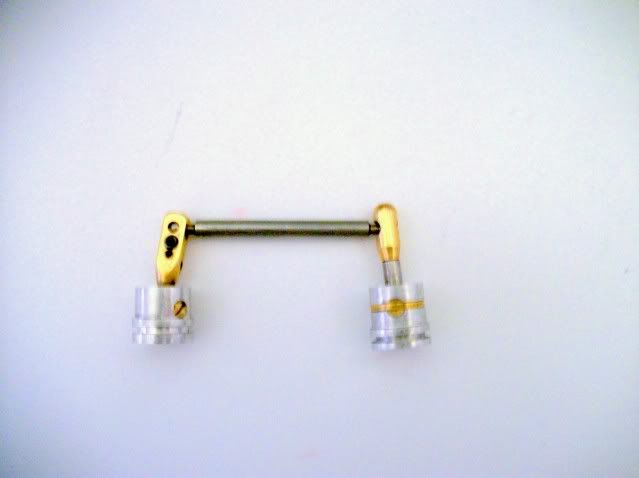
The design on the right is assembled and adjusted with a #8-32 set screw in the top end. The end of the screw has a socket which forms one side of the ball socket in direct contact with the ball. Once assembled, the screw is not accessible or adjustable and under use the relatively course thread of the screw tends to loosen. The new design on the left uses a #2-56 SHCS through the side and does not contact the face of the ball. Since the adjusting pitch is about 75% finer than the screw in the other design, adjustment is more precise and there is little or no tendency of the screw to loosen. And with the screw on the side it is possible to design an access port in the piston skirt and the cylinder wall for fine adjusment and to take up for wear without disassembling the engine.

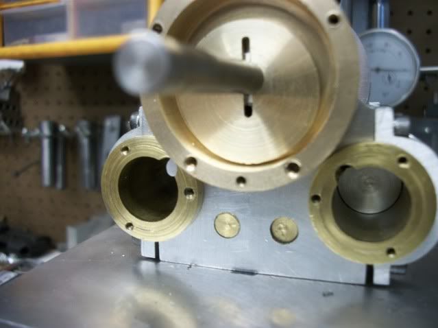
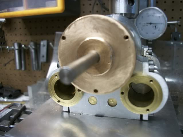
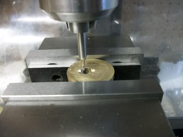
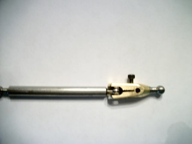
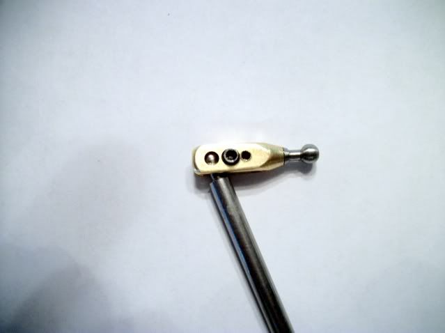
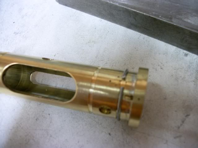
In the second pic, the adjusting screw is visible and to the right is another empty hole in the side of the clamp. This hole is for a jack screw to assist in assembly.

marleytowel010.jpg


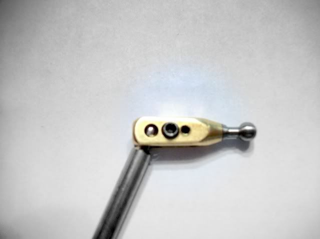
It is used to force the jaws of the clamp apart so that the ball can be inserted without force. Once the ball is in position, the jack screw is backed out and the jaws of the socket close around the ball loosely. The jack screw is then completely remove and placed in the clamp screw hole where it is used to close the socket clamp around the ball untill all backlash is eliminated without adding friction to the joint.

marleytowel006.jpg


marleytowel007.jpg


marleytowel008.jpg


marleytowel009.jpg


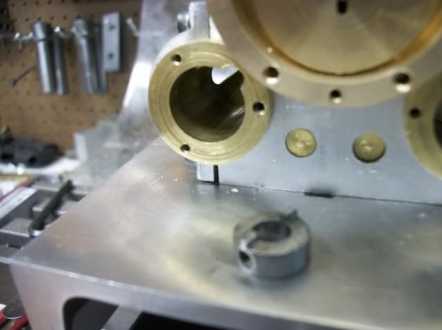
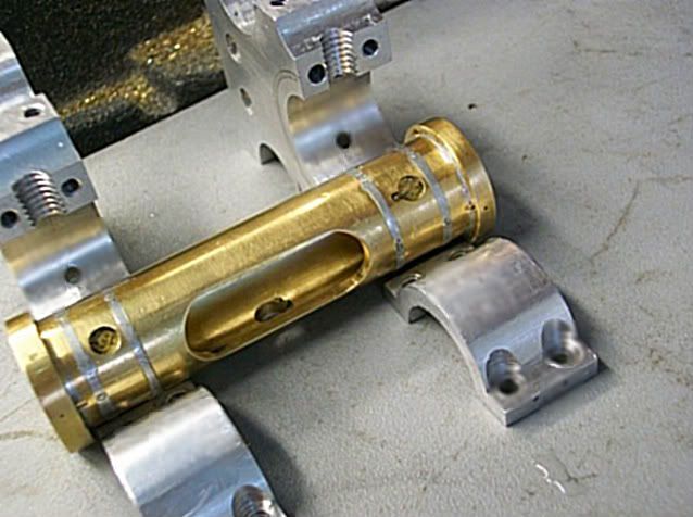
The resulting ball joint is tight with almost no backlash and very little friction. It has good range of movement and is reliable and adjustable.

It is a little clunkier looking and maybe slightly heavier. I don't think the weight difference is enough to affect engine balance and it will be mostly hidden from view.

Now on to other things.

Jerry
 
This build seems to go forward and then backward. I may be jumping around a bit but age rattles your focus some. From a previous build, I knew that this design had a potential problem with air leaks at the cylinder to frame joint. Air pressure from the valve (to be show in a later post) is routed to the cylinders through passages drilled in the end frames. The cylinders actually form part of the structural frame. Any misalignment in the end frames will translate into a bad seat and air leak.

I had thought that a paper head gasket would solve the problem but with some of the other problems that I encountered, paper couldn't stand up to all the assembly/dissasembly so I needed something more rugged and reliable.

Rubber o-rings got some thought but in this diameter ther is nothing less than 1/16" thick and a groove that deep around the cylinder would intercept the air passage that is drilled in the cylinder. The groove can't be any deeper than 1/32". I tried using the shallow groove and wrapping it with teflon tape or graphite yarn and while either of them could be made to work on one groove, getting four grooves wrapped and assembled on each cylinder was a PITA.

EUREEKA! How about soft metal! Solid core solder. Cut to length, hammered into the groove and clamped with the caps. It flows into the groove as it is compressed under the cap and fills any gap between the cylinder and the frame/clamp. It seems to form a good air seal and stands up to repeated assembly/disassembly cycles.

Here are some pictures, I hope it makes sense,

orings006.jpg


orings009.jpg


orings012.jpg


orings013.jpg


orings014.jpg


orings008.jpg


orings011.jpg


Thanks for watching 2834

Jerry
 
Jerry

It looks to me like a brilliant solution to what was a difficult problem to solve. Lets hope that puts you one step up in the forward direction. It is not a question of if you have an Encabulator but when you have an Encabulator. :bow:

Cheers :)

Don

 
Thanks for the comment, Don. I am making progress although much of it is circular. As my Uncle Buzz used to say, "The most important thing is to look busy."

Jerry 2943
 
Are we still busy Jerry? ;D


How's it going buddy?

Dave

 
Thanks for asking, Dave. I am indeed busy and the Encabulator is progressing. Working on it seems to have become as important as finishing it. I keep redesigning and remaking parts. That is not a bad thing. This is not a model of an existing machine or a build from plans. Very little of it is based on other engines. As such, I am free to change and improve as I go. The piston rod ball joint is an example of that. Redesigned and remade at least three times.

The valve design has changed at least that many times, and is undergoing major change now. I think I finally got it right! It is a truly unique design but it doesn't relate directly to what other people are doing so I haven't posted it. For several years, I have been looking for a well engineered, and effective design for a rotary valve and this may be it.

If it works out I'll post it.

Jerry
 
I'd post it even if is doesn't! You hang in there we all know explicitly how difficult it is to align the muffler bearings to exact magnetic north!

;D
In any event, I'd like to see it!

Dave

 
steamer said:
we all know explicitly how difficult it is to align the muffler bearings to exact magnetic north!

That's because it keeps moving ;)

Best Regards
Bob
 
OK Dave, here's the valve.

A few years ago, I posted a build of a three cylinder axial engine (Z-shaft) using this rotary slide valve.

threecylinders011.jpg


The eccentric moves a valve ring within the circular housing that alternately connects the cylinder port with the steam and exhaust ports. It was an attempt to translate the features of the D-slide valve. It did work and the engine ran fine and I used it in some other axial engines but was not totally satisfied that it worked like a D valve.

One of the features of the D valve is that the valve body is held against the face of the valve by pressure in the valve chest and is self adjusting for wear. My rotary valve did not work that way. The valve ring was held against the valve face by pressure from the valve cover. The valve face, the cover and the ring had to be carefully lapped to get it to work. performance improved as the valve seated itself during break in and friction was reduced.

Here is an animated cad presentation.
http://screencast.com/t/XcAUHWQR

I never ran the engine very long but I always had the feeling that wear would reduce the contact pressure and lead to blow by to the exhaust. I know my engines will not be subjected to heavy loads or long duty cycles but that's not the point. The engineering and design is important. If I just wanted to build something that turns by air pressure, I could make a pinwheel.

My first design for the Encabulator used ordinary rotary valves of the type with flats on the shaft to distribute air pressure. These valves are always subject to leakage and wear and are not at all interesting but my concentration was on refining the double acting piston and achieving four evenly spaced power strokes per revolution with what appears to be an unbalanced configuration. The geometry involved took precedence over the valve, and I still had no new ideas for the valve anyway.

The Pizza delivery is here so I'm going to post this and continue the narrative later.

Jerry
 
OK, more valve stuff. The problem with my previous design is the two piece eccentric/ring construction. The pressure differential that holds the valve against the face does not act on the ring and is therefore ineffective. The new design has the eccentric and ring as a single piece and is a sliding fit on the shaft and is analogous to the valve body in a D valve. The valve is rotated by a dog that is held to the shaft by a grub screw. The dog only rotates the valve body, it does not force it against the face (just like the cross piece in a D valve), it is set up with a slight clearance so that the valve body can float.

This is a view into the valve chest. The hole closest to the shaft is the exhaust port. The two holes that align with the cylinders are the cylinder ports that connect to the head of each cylinder. The steam or air pressure will inter the valve chest through a pipe at the bottom of the valve chest. The inside of the valve body will always be over the exhaust port and will therefore be at a lower pressure than the outside of the valve body. As the valve body rotates, the cylinder ports will alternate between the exhaust side and the pressure side of the contact surface.

The valve chest and face are silicon bronze. The valve body is Brass 360. The dog is cast iron. The shaft is 303 SS.

Here are some pics of the assembly.

This is the valve body fitted to the shaft. It is turned back to front so that you can see the contact face and the cavity.
valverevised005.jpg


Here it is turned the right way with the contact surface against the face. The slots at top and bottom accept the dog teeth.
valverevised006.jpg


This is the cast iron dog. Teeth are visible as is the grub screw hole.
valverevised007.jpg


Here is the dog fitted to the shaft with the teeth engaging the slot.
valverevised008.jpg


This view shows the valve rotated so that the visible cylinder port is full open to pressure air and the other cylinder port has just closed and is beginning to open to the exhaust side.
valverevised009.jpg


And here is the valve cover fitted.
valverevised010.jpg


And the flywheel.
valverevised011.jpg


And a general assemble with base.
valverevised012.jpg


Piping and controls have yet to be decided on

The differences in the new valve and the previous version may appear to be superficial but I think it worth the small detour to make the revision, and when it is running, I will be happier knowing that it includes the MarkIII revisions. Linear Reluctance should be enhanced. The effect on depleneration is as yet unknown.

Jerry

PS. I guess it is worth mentioning that there is an identical valve at the opposite end.

 
Thanks Jerry!

Thats must be a tough valve to seal. The valve face must be dead square to the shaft to seal tight of the shaft will want to lift the valve on one side. Is there a bit of play in the valve on the estabulation shaft? ::)


Dave
 
Dave

I believe that the valve face is square to the shaft. It looks like this.

2cyldoubleactingvalveassy.jpg


The face is integral with the bearing. That's why it is bronze. I'm not sure that brass is the right material for the valve riding against the bronze. I have some 7075 Alu that I could use, and also some cast iron. What do you think?

There is some play between the valve and the shaft. The dog is fixed to the shaft, but the valve itself can float. If air pressure is enough to hold a D valve against the seat, it should be enough to do the same here. But that's why I said "If it works"

 
You could try Teflon or Delrin for the valve if your only running with air.

If your running with steam, I would put a iron or SS thin disk in and use the brass valve

Dave
 
Thanks Dave,

I can't use teflon for the valve. The valve is actually a two part assembly that is soldered together. I am in the process of assembling one now so I will get a pic when I get to the shop.

I don't think I will ever use steam unless I find a boiler in my Christmas Stocking.

I thought about using a thin disk in there but there is not enough depth. If I go that way, I will have to turn the bronze housing flush with the face and add a separate outer ring with additional depth. There may be other good reasons for doing that. How would you go about fixing a CI disk to the bronze face so that it remains square to the shaft bore and doesn't rotate?

Jerry
 
hmmm Don't know. I suspect small flat head screws sunk below surface.


I re-read and you state that you used silicon bronze....I only saw the bronze part. ::)

Silicon bronze is tough stuff.....I'd let it go at that with the brass valve and see what happens....I bet the guy who built it would make another if it fails at a very reasonable charge.. ;D


Dave
 
This is why the valve is a two piece assembly. I couldn't think of a way to machine the cavity as shown here:

morevalve018.jpg


So it starts as one piece with the cavity. The eccentric is drilled 3/8" diameter in the mill and the plug is turned to 3/8 with a shoulder turned to .400". The length of the shoulder is equal to the depth of the cavity (.070") The plug is then soldered into the valve. After cleanup, the assembly is returned to the mill.

morevalve001.jpg

morevalve002.jpg


The plug is oriented by eye to lie on the "X" axis. The part is centered on the "Y" axis by halving the distance between the vice faces.
morevalve007.jpg


Now with the finder on the "X" axis, the part is centered by halving the dimension by locating the two oposite edges.
morevalve008.jpg

morevalve010.jpg


It is then offset in the "X" direction by the amount of the eccentric dimension.
morevalve011.jpg


It appears to be centered on the plug but since the plug was oriented by eyeball its only close, but in this case, close really is good enough. I'm about to drill the shaft hole and it just needs to be offset from the center of the valve disc by the amount of eccentric throw (.115") which is also the width of the valve contact face.
morevalve013.jpg


The hole was drilled 15/32" and finished with a 1/4" end mill.

The part was then inverted in the mill and the slots for the drive dog milled 1/16" wide and 1/16" deep.
morevalve015.jpg


The primary purpose of the plug is to provide material on the cavity side to prevent break through of the slot into the cavity. The shaft hole is now square to the back side of the valve so now the valve is returned to the lathe where it is held with the back face against a freshly faced mandrel by the live center and the valve contact surface faced so that it is now parallel to the back face and square to the shaft bore.
morevalve016.jpg


Here it is installed and being driven by the dog. If you turn the sound up, you can clearly make out the desired "POKETAH-POKETAH-POKETAH". This is coming from the cyclical contact of the dingle arm with the spurthing bearings. I am thinking about hollowing out the spurthing bearings to enhance the sound. What do you think?


Jerry

Jerry
 
Well! Who would want an over weight Spurthing bearing! My god man have you no scruples!?

;D....I love this thread.... :big:

Dave
 

The hole was drilled 15/32" and finished with a 1/4" end mill

That's a very fine cut indeed

Keep up the great work

Kind regards

Malcolm
 
Malcolm

I have found that by drilling oversize first, the finish cut can be made at high speed with very little load on the mill and almost no chatter. Results may vary depending on the material.

Jerry
 
Back
Top