Vega 9cc v twin

Home Model Engine Machinist Forum

Help Support Home Model Engine Machinist Forum:

This site may earn a commission from merchant affiliate links, including eBay, Amazon, and others.
NickG said:
Nice work peter. Lapping is something i've never really got to grips with. I tried making a wooden dowel lap with wet & dry paper wrapped around it for my flame licker, it resulted in a good finish but a non round non parallel bore. So I used an adjustable reamer with plenty of oil and that gave me good results and an acceptable finish.

The problem I see with your lap is you have to use it at every point in the bore the same amount, where as the reamer is the same diameter all along. Having said that, it seems to have worked well for you.

Nick

Thanks Nick, I used a wooden dowel and wet and dry on my oscillators bore which is only 1/4 inch and that worked.
This is my first i/c build so dont know if I have it right yet but having to lap every part of the bore gave me no real problem as the amount removed is so small and it just seemed to work well. I'm hoping anyway.
Couldn't find a fingers crossed smiley.
Peter.
 
Thanks peter, might have to try this method for my next project if I don't have a reamer the right size.

I will keep my fingers crossed too.

Nick
 
Hello again folks. I can’t believe it’s been a year since I did any work on this (or anything else). After distractions and lack of motivation I am pleased to say I have made some progress these last couple of weeks.
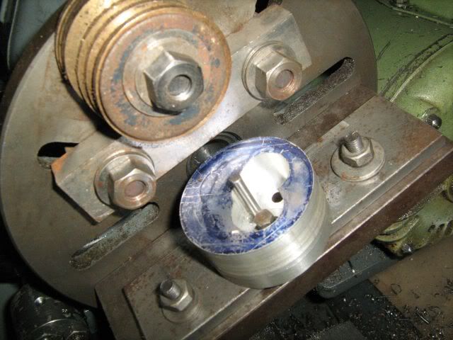
I had difficulty setting up to machine the flats on the timing case. I was trying to set up on the mill with a rotary table to set the angle but found there just wasn’t the height.
Probably could have got it on the mill somehow but thought I would try on the lathe faceplate which is how I did the crankcase
Timingcase3b.jpg


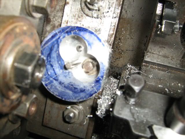
Timingcase3c.jpg


Initially all seemed well until I noticed that the two faces were not at 45degrees. I had positioned the gears and marked the shaft holes as per instructions without thinking that the centres should be along a 45degree line and then used the holes to mount assuming they were at 90 degrees to the face. Luckily there was still enough meat left to reposition and get the angle correct. Hard to explain without showing the drawing but I don’t think it will affect anything important.
Had to set up the mill next to machine away the bottom angles, the sides and the little bit at the top for a bolt. Sorry I didn’t get any photo’s of that bit.
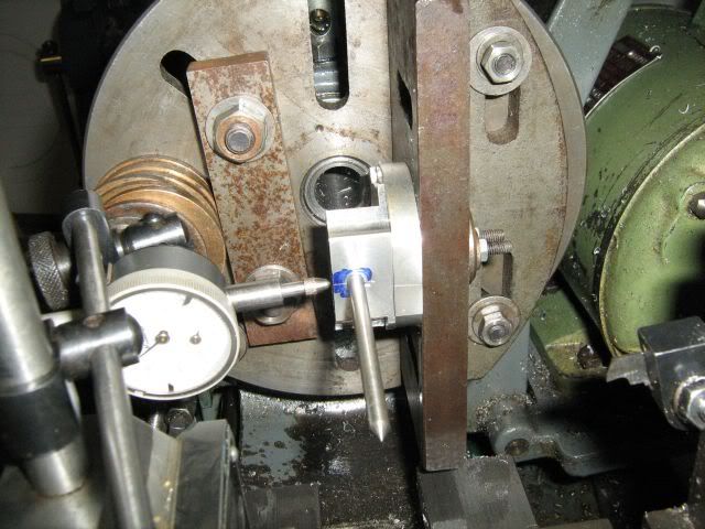
Next I had to mark the centre of the holes for the pushrod exit and bore to 3/8 for the guide. I marked as accurately as I could and put in just enough of a mark to get a point in. Set it true on the faceplate with the dial gauge and wiggler rod. Drilled and reamed a 3/16 hole as that’s the size of my wiggler rod. Place the rod in the hole and set the dial gauge to zero on the face and noted the reading on the cross slide. Wound the slide in the required amount to make contact with the rod and found I was 8 thou out. Tapped the angle plate across to get the dial gauge reading zero and bored to size

Timingcase3d.jpg


Repeated again with the other face.
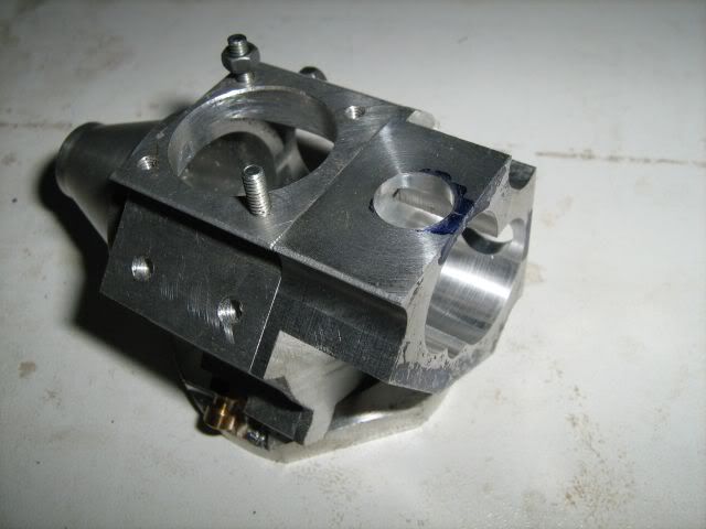
No doubt there are easier ways to get this job done but the end result is all that matters and so far would seem to be ok, which is surprising as I don’t know what I am doing most of the time.
Timingcase3f.jpg


Peter
 
Nice work Peter, that is a really complex component, nice set up work I don't think I'd have the patience for something like that! My project had also just about been a year before I started it up again a couple of weeks ago so in the same boat!

Nick
 
Hi Peter

Nice work and a good looking engine, i'm in Kings Lynn are you
nearby ?

Rgds, Marcus
 
Hello Marcus,

Thanks for the compliments. I'm just on the far side of Norwich.
I see you're building four joined up ones :bow:

Best wishes
Peter

 
I’ve been doing a bit more and have the backplate made,the bearings fitted in the crankcase and produced some cams .
Had a major oh no! moment on the crankcase when drilling holes for the two bearing retaining screws. The instruction was to just break through to avoid having to tap a blind hole. I thought I was drilling into a thicker piece than I actually was and not only broke through (which I hadn’t intended to do) but I was half in half out of the piece so I have two grooves down the outside. Cosmetic only so not a total disaster but very annoying.
Sorry this work has been sporadic and I didn’t think to take photos.

For the cams I followed the method described which was to make a hardened master cam and then use it to produce the two pairs needed. All filed by hand.

First The master is held between two buttons to get the base circle then flanks filed to 45degrees and finally blended in for a 1/16 radius at the top. Now we have photos. This is the master cam before hardening.

Mastercam1.jpg


The blanks were turned up and then two lines scribed on at 105 degrees apart

scribingblanks.jpg


One of these is then bolted alongside the master with one line lining up with the top of the master which also has a line on and filed to shape on the one half.

firsthalfshaped.jpg


Then just turn it round,line up the other line at 105 degrees and file away again

secondhalfshaped.jpg


Then do it all again to get two pairs of cams.

twocompletedcams.jpg


The suggestion is that these are just fixed on the shafts with locktite. I am wondering, as doubts have been expressed about this, if I should perhaps try and put a pin in.
Any ideas or comments anyone?

Peter.
 
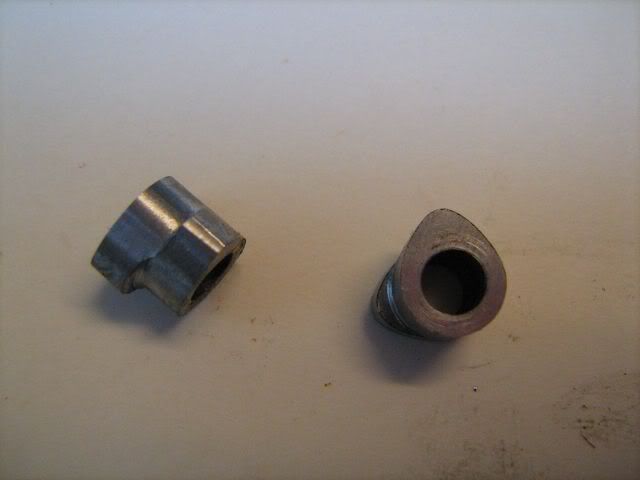
I made cams with a hub and set screw for my SENTINEL engine. Locktite works but depends on rotating inertia of the lobes striking the valves under spring pressure. Will the bond hold? I don't know the capability's of the VEGA but high RPM motors undoubtedly have higher spring pressures that may kick back a bonded lobe on a shaft. Epoxy a better bond and pins a positive tie to the cam shaft. Sentinel is a low RPM engine and no lobe slipage on the cam shaft with set screws. With fixed cam timing, the pinning wins over bonding and is an easy operation. Dave.
IMG_0178.jpg
IMG_0246.jpg
 
Hi Mo,

Great Work! Your a "Lathe Centric" guy like me....much rather mount up a faceplate than a mill vice.

Great job!

Dave
 
I have used the loctite for my Lynx engine and it didnt hold, maybe because i used the green loctite. I have heard that to acheive permanent bonds the blue one is better maybe i should have tried it. About the pinning, i did it as well and the cam shaft fails and snapped from the pin hole. At last i machiend the whole cam from one piece and till now its still in one piece :)

Drei
 
Many thanks for the input fellas. I am thinking that there is room for a set screw/grub screw on the centre of the two cams. That combined with the proper shaftlock I bought hopefully will do the trick.


ttfn
Peter
 
Again it has been too long since I made any progress on this engine.
I managed to make the rockers a few weeks ago but have only just got round to uploading the photos.
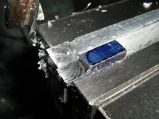
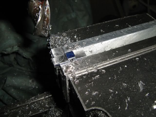
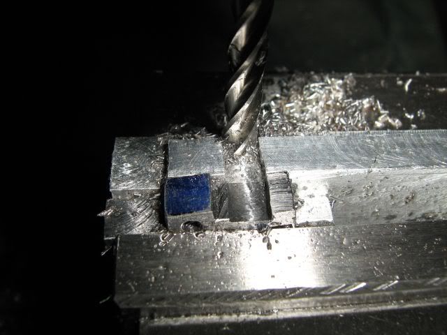
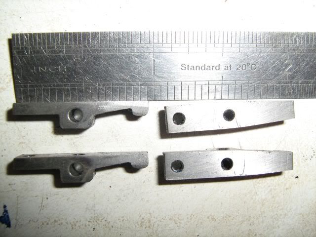
I milled a length of steel to 1/4x3/16 and drilled and reamed the holes for the shaft before cutting to length.
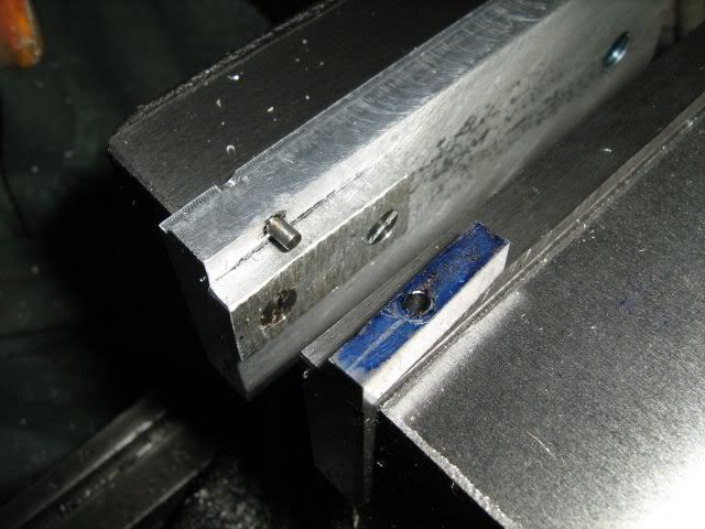
I decided to hold them for further ops by fitting a guide and pin to one end of a soft jaw in the vice. The rocker is the blued piece with the hole.

http://i649.photobucket.com/albums/uu218/scruffyoik/Vega/rockersjig.jpg[/img]]

Then it was a case of cutting each side of the pivot point before cutting away one end of the support so I could machine the angle to make the pad for the valve end. The photos should explain better that my words

rockersfirstcut.jpg

rockerssecondcut.jpg

rockersthirdcut2.jpg


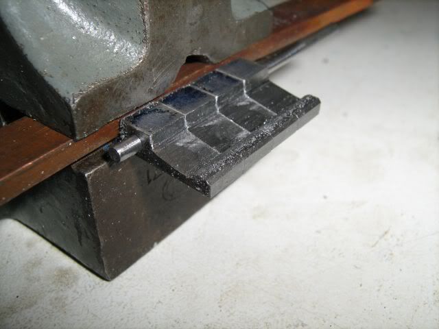
After drilling and tapping the holes for the 8ba adjusters I held them in a small vice to hand file the finished shape

rockersshaping2.jpg


The hole in the centre is a countersunk small oil hole

rockersfinished.jpg


Just remains to case harden them.


Peter
 
Again it has been too long since I made any progress on this engine.
I managed to make the rockers a few weeks ago but have only just got round to uploading the photos.
I milled a length of steel to 1/4x3/16 and drilled and reamed the holes for the shaft before cutting to length.
I decided to hold them for further ops by fitting a guide and pin to one end of a soft jaw in the vice. The rocker is the blued piece with the hole.

http://i649.photobucket.com/albums/uu218/scruffyoik/Vega/rockersjig.jpg[/img]]

Then it was a case of cutting each side of the pivot point before cutting away one end of the support so I could machine the angle to make the pad for the valve end. The photos should explain better that my words

After drilling and tapping the holes for the 8ba adjusters I held them in a small vice to hand file the finished shape

The hole in the centre is a countersunk small oil hole

Just remains to case harden them.

Peter

Peter

I have just got the Model Engineer issues for this engine and have started to draw it in alibre. There seems to be dimensions missing for the length of the crankcase, do you have a drawing of the crankcase that you used to make the crankcase.

Mike
 
Peter

I have just got the Model Engineer issues for this engine and have started to draw it in alibre. There seems to be dimensions missing for the length of the crankcase, do you have a drawing of the crankcase that you used to make the crankcase.

Mike

Hello Mike, sorry I have only just seen this. No drawing I'm afraid and I can't remeber what I did now. I think I probably decided that the length of the bit that is missing didn't matter as long as the crankshaft fitted.
You have probably worked it out by now. I hope it all goes well for you.

Regards
Peter
 
Peter

Yes I have it all drawn in Alibre now. Going to start it after I have finished the Nemett lynx I am working on.

I am going to make it twice full size.

Thanks

Mike
 
  • Like
Reactions: gus
Back
Top