
You are using an out of date browser. It may not display this or other websites correctly.
You should upgrade or use an alternative browser.
You should upgrade or use an alternative browser.
Building Jerry's Donkey
- Thread starter Captain Jerry
- Start date


Help Support Home Model Engine Machinist Forum:
This site may earn a commission from merchant affiliate
links, including eBay, Amazon, and others.
- Joined
- Dec 2, 2008
- Messages
- 971
- Reaction score
- 8
Thanks Kevin, glad you are interested. Executions usually occur at dawn and since the Governor hasn't called, I guess the execution is still on.
Not brow beating at all Dave. I really meant it when I said thanks for keeping me on the straight and narrow or should I say bent and crooked. Now that I am committed to a solid rod at the outer end, I have to start thinking seriously about the other end. The only place left for valve adjustment is the nut in the valve slide. The rod end will be threaded #2-56 screwed into a bar in the valve slide. The valve position can be adjusted in 1/2 turn increments of the bar or about .009" which ought to be fine enough but it is the procedure that is puzzling me. If the rod were straight you would just unpin the eccentric and give the rod a few turns or a 1/2 turn and re-pin it. With the flat end of the rod trapped in the guide that will have to be released but that means the adjustment increment is one full turn or .018" which may be a little coarse. No matter what, it looks like fine tuning is going to be a pain in the butt. There may be a better way to design the valve end of the rod but I can't see it yet.
Any suggestions?
Jerry
Captain Jerry said:Thanks Kevin, glad you are interested. Executions usually occur at dawn and since the Governor hasn't called, I guess the execution is still on.
Not brow beating at all Dave. I really meant it when I said thanks for keeping me on the straight and narrow or should I say bent and crooked. Now that I am committed to a solid rod at the outer end, I have to start thinking seriously about the other end. The only place left for valve adjustment is the nut in the valve slide. The rod end will be threaded #2-56 screwed into a bar in the valve slide. The valve position can be adjusted in 1/2 turn increments of the bar or about .009" which ought to be fine enough but it is the procedure that is puzzling me. If the rod were straight you would just unpin the eccentric and give the rod a few turns or a 1/2 turn and re-pin it. With the flat end of the rod trapped in the guide that will have to be released but that means the adjustment increment is one full turn or .018" which may be a little coarse. No matter what, it looks like fine tuning is going to be a pain in the butt. There may be a better way to design the valve end of the rod but I can't see it yet.
Any suggestions?
Jerry
Jerry,
How about using a turnbuckle nut in the middle of the rod for adjusting the length. I believe that you would need to cut both right and left handed threads.
SAM
- Joined
- Dec 2, 2008
- Messages
- 971
- Reaction score
- 8
Sam
A turnbuckle is a possibility. The left hand thread is the hangup due to the size (.093" rod dia.) but it is worth some thought. Thanks for the input.
Jerry
A turnbuckle is a possibility. The left hand thread is the hangup due to the size (.093" rod dia.) but it is worth some thought. Thanks for the input.
Jerry
Maryak
Well-Known Member
- Joined
- Sep 12, 2008
- Messages
- 4,990
- Reaction score
- 77
Jerry,
The back of the valve, assuming it's a D valve, has a 2 grooves along the centre lines in the form of a cross. One groove takes the threaded valve rod and the X groove accepts a nut which can be screwed either way to adjust the position of the valve relative to the ports. That way a normal thread is all that's required.
If it's a piston valve the centre may be threaded and the valve rod screwed onto it. the valve is turned by means of a couple of holes in the top and locked in place with a nut and a copper washer under it, (to seal the piston).
Hope you get my drift, if not I will try a C-o-C.
Best Regards
Bob
- Joined
- Dec 2, 2008
- Messages
- 971
- Reaction score
- 8
Thanks for the response, Bob. The valve is a "D" slide valve and I have built it with a flat bar with a threaded hole that sits in the cross slot in the back of the valve. I used the bar instead of a hex nut because the space between the valve rod and the bottom of the slot meant that a normal nut would not fit. I also thought that using a bar that could not turn would eliminate any creep in the adjustment without needing a jam nut. I also thought that the bar would keep the valve square to the rod. I may have out smarted myself (easy to do). I guess I shouldn't worry about creep with a tight fitting 56 TPI thread so I need to see if I can fit a nut in place of the bar. There is not much space between the valve cavity and the slot.
Jerry
Jerry
- Joined
- Dec 2, 2008
- Messages
- 971
- Reaction score
- 8
Hi Y'all
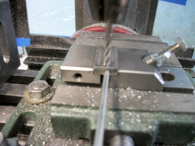
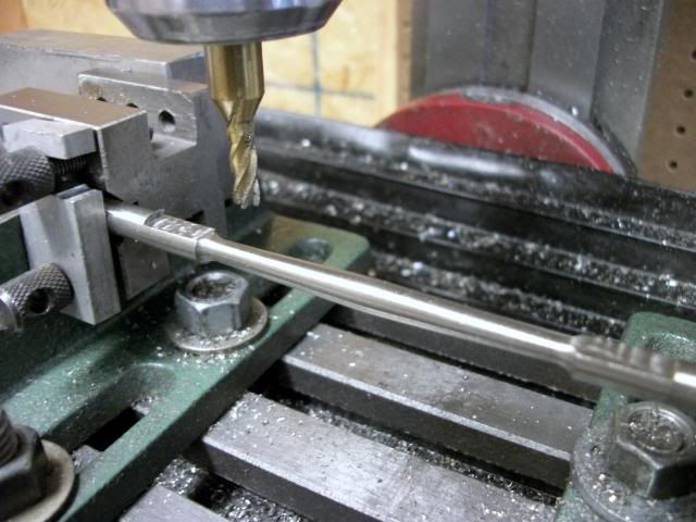
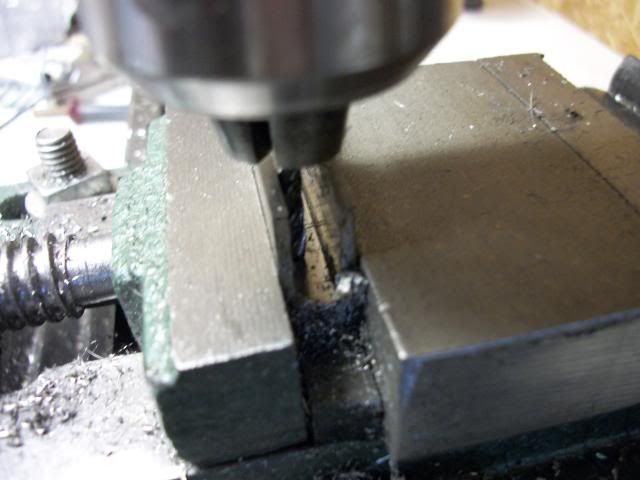
I'm back from my travels and into the shop. Long drives ( 12 hrs Florida to western Tennessee) gives a lot of thinking time while my wife naps, so when I got to the shop this morning, I had a plan. It mostly worked. Here is the result:
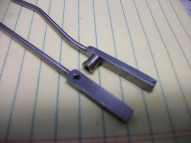
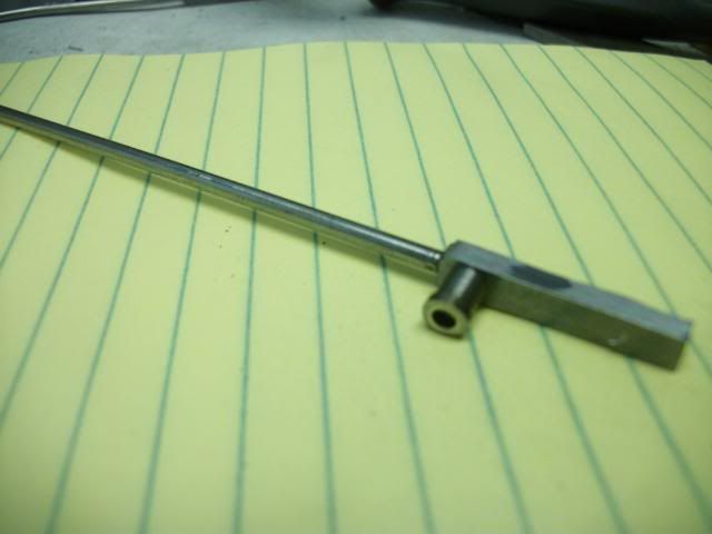
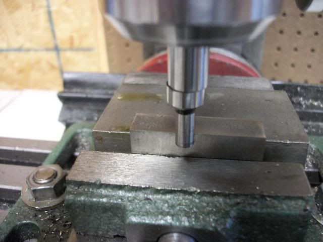
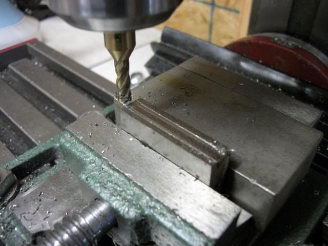
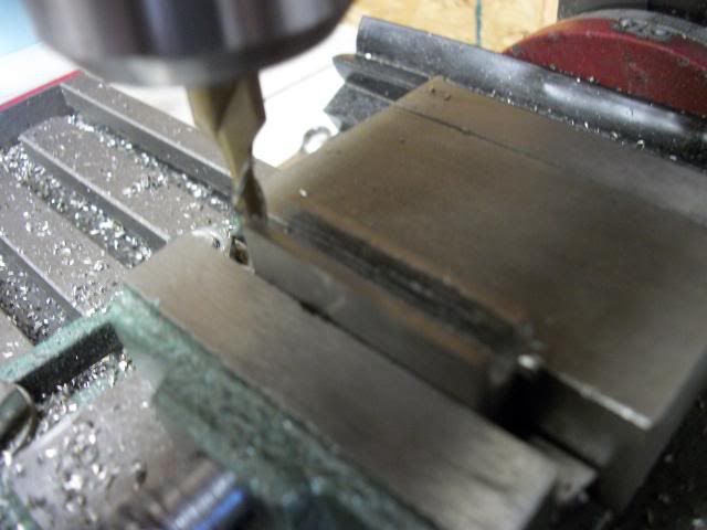
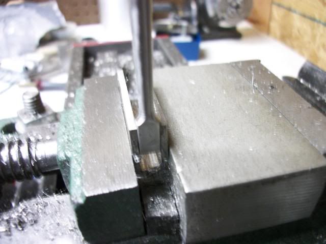
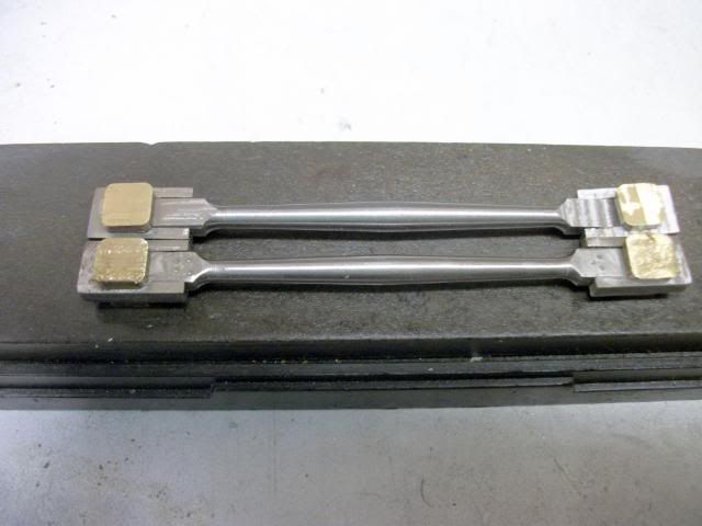
The piece on the right is the trial piece and it includes the necessary bends and the attached pivot for the small end of the eccentric rod. The piece on the left (and the one that I will finish tomorrow) will be left straight until the final length can be worked out. The straight one shows how close the hole for the pivot is to the joint end of the rod and the bar. The hole is drilled and tapped for a #4-40 screw. The hole for the screw is the same diameter as the valve rod and it is only about .100" from the end of the bar. I would have had to use a #2-56 thread if I tried to screw the rod into the bar and I don't think it would have been strong enough, even with loctite. There might have been enough material for a good silver-solder joint but I wasn't real sure so this is how I did it:
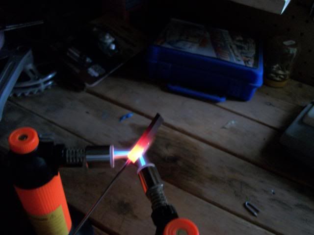
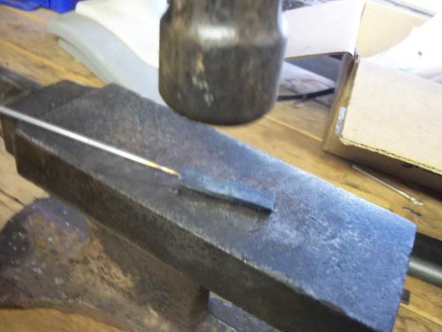
How about that for stress relief? Not the steel, ME! There is something really relaxing and soothing about heating a piece of metal till it glows and then whacking the crap out of it with a hammer. A few cycles of heating and whacking and I was feeling pretty relieved.
With the two tiny little torches you see, I could not get the metal to the white heat needed to weld the joint, but with the red heat, I was able to reduce the thickness of the flat steel by about 1/3 which makes me think that the round rod was also flattened and deformed in the hole forming a really good mechanical bond.
A little work on the mill brought the bar to final size and then it was drilled and tapped for the pivot and my mother's brother is Robert.
I'm going to relax with a little Jack Daniels (I've been to Tennessee).
Jerry
I'm back from my travels and into the shop. Long drives ( 12 hrs Florida to western Tennessee) gives a lot of thinking time while my wife naps, so when I got to the shop this morning, I had a plan. It mostly worked. Here is the result:
The piece on the right is the trial piece and it includes the necessary bends and the attached pivot for the small end of the eccentric rod. The piece on the left (and the one that I will finish tomorrow) will be left straight until the final length can be worked out. The straight one shows how close the hole for the pivot is to the joint end of the rod and the bar. The hole is drilled and tapped for a #4-40 screw. The hole for the screw is the same diameter as the valve rod and it is only about .100" from the end of the bar. I would have had to use a #2-56 thread if I tried to screw the rod into the bar and I don't think it would have been strong enough, even with loctite. There might have been enough material for a good silver-solder joint but I wasn't real sure so this is how I did it:
How about that for stress relief? Not the steel, ME! There is something really relaxing and soothing about heating a piece of metal till it glows and then whacking the crap out of it with a hammer. A few cycles of heating and whacking and I was feeling pretty relieved.
With the two tiny little torches you see, I could not get the metal to the white heat needed to weld the joint, but with the red heat, I was able to reduce the thickness of the flat steel by about 1/3 which makes me think that the round rod was also flattened and deformed in the hole forming a really good mechanical bond.
A little work on the mill brought the bar to final size and then it was drilled and tapped for the pivot and my mother's brother is Robert.
I'm going to relax with a little Jack Daniels (I've been to Tennessee).
Jerry
- Joined
- Dec 2, 2008
- Messages
- 971
- Reaction score
- 8
Thanks Dave. As usual, the things you worry most about don't seem so difficult after you get through it. And I learned something new in the process. I would say that is a forgery ;D but it is not, its genuine.
Just a note on the strength of the joint. The rod is 303 stainless and the bar is mild steel. I gripped the rod in the bench vise and grabbed the bar with vise grips and twisted. The joint held, the rod snapped at the joint. I had left no room between the vise and the joint so there was not much room for the rod to flex. I made another using music wire instead of stainless and put it in the vise with about 2 inches between the vise and the joint. I got two full twists in the wire before it snapped. Again at the joint.
I'm sure I'll find other uses for this technique, mostly because it's great fun!
Thanks for your words of encouragement.
Jerry
- Joined
- Dec 2, 2008
- Messages
- 971
- Reaction score
- 8
Here is a challenge for anyone. Hold a piece of hot steel in one hand. Hold a camera in the other hand. Swing a hammer with the other other hand. AND do it while the red heat is still on the steel. I failed. The pic is a fake.
Jerry
Jerry
- Joined
- Dec 2, 2008
- Messages
- 971
- Reaction score
- 8
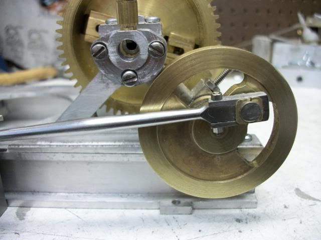
Speaking of rods, its time to make the connecting rods. I started the process on Friday and fiddled with it all weekend. I have picked up a new term ( new to me) "fishbellied". Since I don't really know the correct proportions for fishbellied rods, I posted a "Question" friday night but the forum was very quiet and I was impatient so Saturday I put a length of 30d steel in the lathe and eye-balled a double taper and then took a piece of mild/merchant steel and worked out the rod end cap. The bushing and the crank pin followed:
I was pretty much satisfied with the results except its the wrong length and the wrong material. The wrong length because I was just experimenting and the wrong material for the same reason. I have a piece of 1/4" OD 303 stainless that is intended for the rods. The rod end cap will come from a piece of stainless steel that I picked up from the scrapyard with no pedigree.
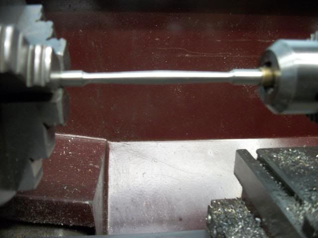
There was nothing really tricky about the rod once I had the right dimensions. I ground a radius on the end of a 1/4" HSS tool bit and plunge cut to just short of final size at the narrow neck on the rod. With the compound set to about 1.5 deg using a protractor. With the carriage locked, I backed the tool away from the chuck using the compound, cutting a taper. I continued backing away from the chuck after the cutter stopped cutting to give me room to advance the cross slide.
Then I took a measurement at the narrow point, subtracted the final size (.145") and divided by two to get the amount of cross slide infeed. I cranked it in and then using the compound, I advanced it towards the chuck. When it got to the neck, the full radius of the cutter made contact with the shoulder and that all it took. I reversed the piece in the lathe and did the same thing for the other end. The final finished length of the rod is 3.10" and there is a .5" flat section at each end so the distance between the shoulders is 2.10". I hit that with a layout mark on the second taper. I left plenty of stock at either end for the flat and to hold the part while milling the flats.
My small center drill shed its point a few days ago and while waiting for a replacement, I used another approach for outboard support. I gripped a 1/4"ID oillite bushing in the tailstock chuck ad since the stock was 1/4" polished SS, it was plenty of support.
The next step was to mill the flats on both end of the rod. I set the ends of the rod in a pair of "V" blocks to keep the faces in register and then held each of the "V" blocks in the a vice ( I have 2, cheap) on the mill table. The blocks could have been clamped to the table got them up high enough to clear the "V" block clamp screws when milling the fourth side of the flats.
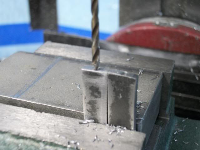
With the flats milled on both rods, it was time to tackle the end caps. The scrapyard SS was in the form of a block 1.25" wide, .75" thick and 2" long. A short excersize session with the hacksaw yielded a piece off of the end that is .375" thick after squaring it up on the mill. Here it is in the vise with the edge finder in preparation for centering the spindle over the long face.
Now i will mill a 3/4" deep slot the length of the piece. I did not want to risk a 1/8" dia carbide bit. To rough out the cut, I used a 3/16" coated HSS bit taking cuts of .050" with lubrication. Here is the first pass.
I did not like the performance of the 4-flute bit so I switched to a 2-flute bit. It doesn't get much use so it is probable sharper and the chip clearance should be better as the slot gets deeper.
Much better. Now its just a lot of cranking and cleaning. Once I got to the final depth, I switched to a 1/8" carbide bit and increased the RPM and brought the slot to final width with fine cuts.
I have to go watch "The Event" (American TV). If I miss the start, I'll never know what they are talking about. I'll be back after 10:00 o'clock.
Jerry
I was pretty much satisfied with the results except its the wrong length and the wrong material. The wrong length because I was just experimenting and the wrong material for the same reason. I have a piece of 1/4" OD 303 stainless that is intended for the rods. The rod end cap will come from a piece of stainless steel that I picked up from the scrapyard with no pedigree.
There was nothing really tricky about the rod once I had the right dimensions. I ground a radius on the end of a 1/4" HSS tool bit and plunge cut to just short of final size at the narrow neck on the rod. With the compound set to about 1.5 deg using a protractor. With the carriage locked, I backed the tool away from the chuck using the compound, cutting a taper. I continued backing away from the chuck after the cutter stopped cutting to give me room to advance the cross slide.
Then I took a measurement at the narrow point, subtracted the final size (.145") and divided by two to get the amount of cross slide infeed. I cranked it in and then using the compound, I advanced it towards the chuck. When it got to the neck, the full radius of the cutter made contact with the shoulder and that all it took. I reversed the piece in the lathe and did the same thing for the other end. The final finished length of the rod is 3.10" and there is a .5" flat section at each end so the distance between the shoulders is 2.10". I hit that with a layout mark on the second taper. I left plenty of stock at either end for the flat and to hold the part while milling the flats.
My small center drill shed its point a few days ago and while waiting for a replacement, I used another approach for outboard support. I gripped a 1/4"ID oillite bushing in the tailstock chuck ad since the stock was 1/4" polished SS, it was plenty of support.
The next step was to mill the flats on both end of the rod. I set the ends of the rod in a pair of "V" blocks to keep the faces in register and then held each of the "V" blocks in the a vice ( I have 2, cheap) on the mill table. The blocks could have been clamped to the table got them up high enough to clear the "V" block clamp screws when milling the fourth side of the flats.
With the flats milled on both rods, it was time to tackle the end caps. The scrapyard SS was in the form of a block 1.25" wide, .75" thick and 2" long. A short excersize session with the hacksaw yielded a piece off of the end that is .375" thick after squaring it up on the mill. Here it is in the vise with the edge finder in preparation for centering the spindle over the long face.
Now i will mill a 3/4" deep slot the length of the piece. I did not want to risk a 1/8" dia carbide bit. To rough out the cut, I used a 3/16" coated HSS bit taking cuts of .050" with lubrication. Here is the first pass.
I did not like the performance of the 4-flute bit so I switched to a 2-flute bit. It doesn't get much use so it is probable sharper and the chip clearance should be better as the slot gets deeper.
Much better. Now its just a lot of cranking and cleaning. Once I got to the final depth, I switched to a 1/8" carbide bit and increased the RPM and brought the slot to final width with fine cuts.
I have to go watch "The Event" (American TV). If I miss the start, I'll never know what they are talking about. I'll be back after 10:00 o'clock.
Jerry
- Joined
- Dec 2, 2008
- Messages
- 971
- Reaction score
- 8
The TV show is over and I'm back.
After checking the fir with the rods, it's just a matter of taking four slices off of the piece, fitting the bushings, which are split square bronze bushings. At this point, I seem to have stopped taking pictures. It got a little bit fiddly and I just forgot. This is where I am now.
I'm not real happy with the bushings an I may remake them. If I do, I'll try to remember pics. Next is to finish the bushings, fit them to the crank pins and then fit the rod end retaining bolts and pins.
Jerry
Maryak
Well-Known Member
- Joined
- Sep 12, 2008
- Messages
- 4,990
- Reaction score
- 77
Jerry,
Very nice rods. :bow: :bow: (one for each).
That's 2 things new to me. Fishbellied - I've made them but didn't know they had a name. The method of mounting the bearings at each end of the rod is a new one for me as well. Maybe it's a USA thing.........I've never seen it on a British engine but perhaps that's because there are many things I've never seen. ;D
Best Regards
Bob
Very nice work Jerry. I had never ran across the term "Fishbellied" before, untill reading it in your thread.---Brian
- Joined
- Dec 2, 2008
- Messages
- 971
- Reaction score
- 8
Thanks for the encouragement, Dave. I'm learning to take enjoyment from the small details and challenges and not hurry to a conclusion. This is an example. The rods became the project.
Bob, I didn't know "fishbellies" either but all of a sudden it popped up in several unrelated posts and even on another forum. The rod end is an interesting detail. What Dave says about "easy to take up on" explains the wedge in this pic of the original:
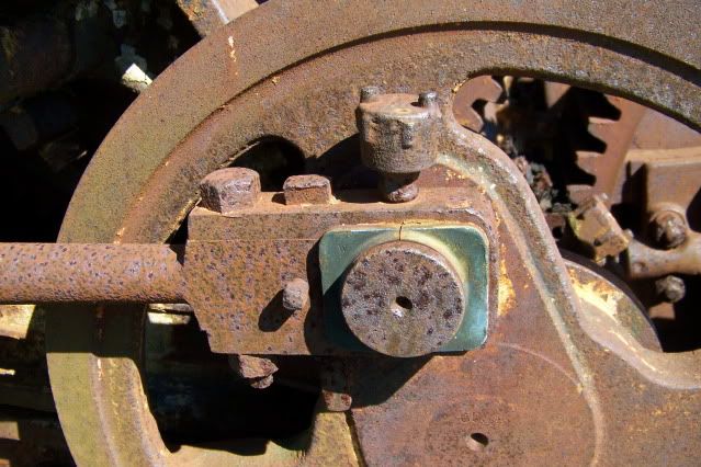
You can see the top of the wedge is slightly mushroomed from hammer taps. These bushings look almost new, with no evident wear. Probably replacements. The AMHoist brochure describes the rods as follows:
"Connecting Rods: Steel, finely finished. End caps securely bolted. Cylinder heads cannot be wrecked"
I have seen cylinder heads "wrecked" when a conventional rod end cap comes loose and the crank journal contacts the shoulder of the rod. This makes the effective length of the rod increase by half the journal diameter and jams the piston into the head. I can't see that happening with this design. Good design and good looking too.
Jerry
Bob, I didn't know "fishbellies" either but all of a sudden it popped up in several unrelated posts and even on another forum. The rod end is an interesting detail. What Dave says about "easy to take up on" explains the wedge in this pic of the original:
You can see the top of the wedge is slightly mushroomed from hammer taps. These bushings look almost new, with no evident wear. Probably replacements. The AMHoist brochure describes the rods as follows:
"Connecting Rods: Steel, finely finished. End caps securely bolted. Cylinder heads cannot be wrecked"
I have seen cylinder heads "wrecked" when a conventional rod end cap comes loose and the crank journal contacts the shoulder of the rod. This makes the effective length of the rod increase by half the journal diameter and jams the piston into the head. I can't see that happening with this design. Good design and good looking too.
Jerry
Similar threads
- Replies
- 75
- Views
- 13K
- Replies
- 14
- Views
- 914
- Replies
- 148
- Views
- 20K