Deals on Alibre

Home Model Engine Machinist Forum

Help Support Home Model Engine Machinist Forum:

This site may earn a commission from merchant affiliate links, including eBay, Amazon, and others.
I was looking at the specs between versions. Atom will import .step while the pro version will import Rhino 3dm, IGES, and parasolid.
And yeah, for little engines Alibre seems to be the better ticket. I can't say anything about CAM options.

Edit: I was looking here at beefier CAM packages they support internally.
https://www.alibre.com/ecosystem-cam/
 
I've been silently watching this thread and learning all I can about the options.

Right now, I'm using an old version of Rhino (v5) and working around its bugs. Alibre sounds like a high point for me. Even though I can upgrade to the current Rhino at a discount (any older version of Rhino gets it), it's $600. $100 for Alibre sounds better (this weekend only).

I'm curious about the the Alibre Workshop combo of CAD and CAM and I'm hoping someone who has played with Workshop can tell me about it.

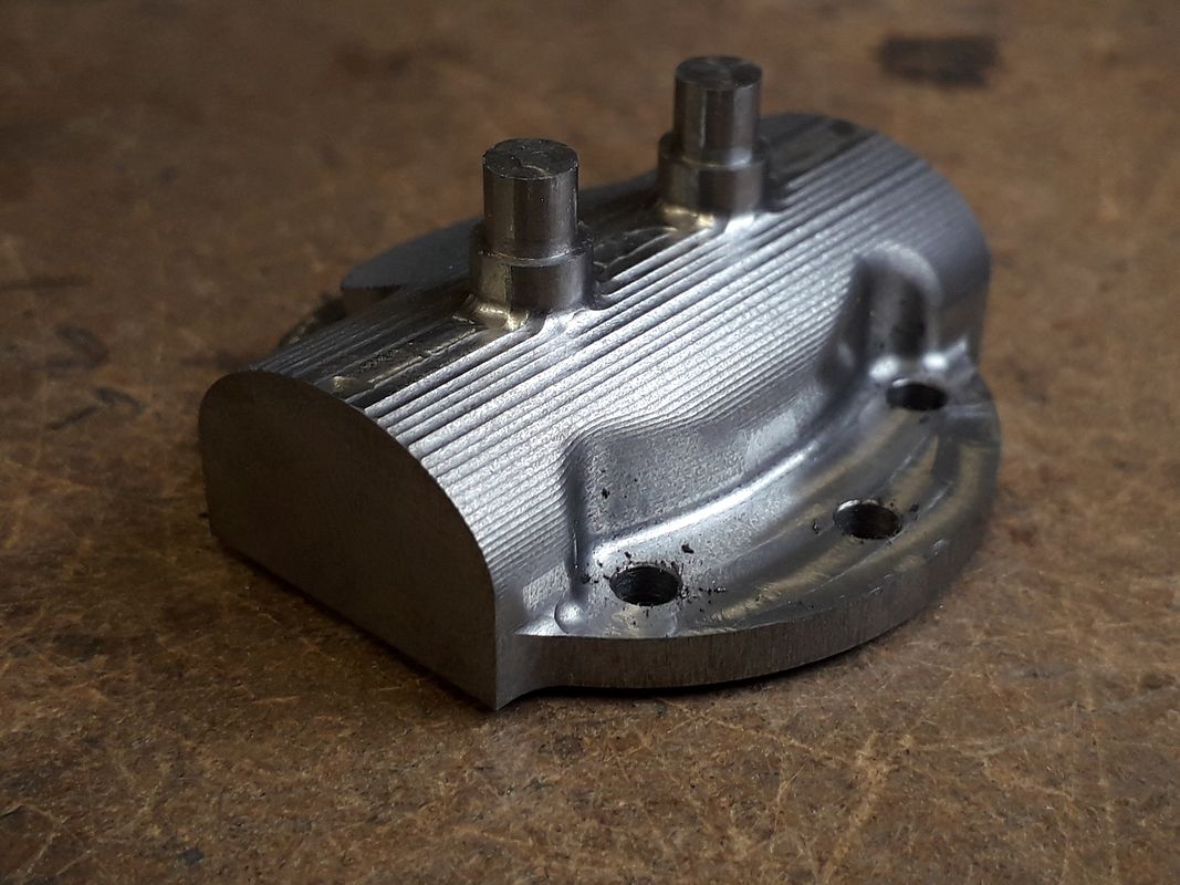
It looks like simple CAM. I also have an old version of DeskProto, which (I think!) has been replaced by the free version and I think of it as good for cutting outlines. I think that's 2.5D CAM. This is picture of the thing about it that annoys me. I don't know the term for it but I think it isn't as good as plain old G-code from the command line in Mach3 I give it a part with a line that's not a straight cut in X or Y, say, and it interpolates a series of X and Y movements. For example, look at the left front of this part that I made a few months ago for the engine I'm working on. I drew a red-orange square around it.

View attachment 131371

The angled surface ends up having very visible "stair steps" on it. They're lighter in color here because of some time I spent with a belt sander removing some of the ripple. I could program that in one line in G-code from the command line, if I figured out the start and end points of the line segment. Lately, I've been writing CAM files by hand because I want the surface to come out smoother. Likewise the raised area on top is halves of two different diameter circles connected by straight line cuts, just not straight in pure X or Y. If you look at the vertical edge right around the middle of the bolt, where it goes into the curve and you can see little steps there, too. In G-code that would come out prettier if you programmed it as two semicircles joined by straight lines, rather than a bunch of little straight lines segments.

I don't know much about what's commercially available. Maybe this is a dream for a CAM program that's beyond what people can program, but having the CAM integrated into the CAD would be the best chance. When I design the part in CAD, I'd specify where those cylinders are centered in 3-space, their diameter and height above the rest of the block. If that information is in the CAD file, the CAM program only needs to know how big the tool you're using is so that it can calculate the 1 radius offset for every point it needs to cut.

Does Workshop act like Deskproto?

Alibre Atom is looking good. I'd rather not open every Rhino file I've got on my drive and save them in a format that Atom can read, but I suppose that's likely no matter which program I use.


Bob
Test whether Atom can open the Rhino files. Alibre at all levels has problems with files one would think would open easily. They start in and then fail. The other thing Alibre cannot do is read an STL file. They say they are evaluating capabilities but I notice it is not mentioned in their next release scheduled for December.
SolidWorks will open STLs although they are not in parametric form when they get in. I've never gone beyond that is trying to work with them so I cannot comment further.
 
  • Like
Reactions: Zeb
Bob I only had a quick play with the trial version of MeshCAM which is what you get in workshop so can't say how well it actually performs when put to work. I did find it was a bit limited in what it could do particularly for 3D, take these two screen shots of that manifold I showed earlier, the first is MeshCAM which really only offered parallel finish with a constant stepover - you can see on the vertical edges of teh flange and where th ebranches come towards the flange there are marked steps. You could get rid of these with a smaller stepover but that adds a lot to the run time.

880232.jpg


Same part in the F360 simulator has a much more even finish, the small blue specs are where it has not removed waste, green the finished surface of teh modelled part (Alibre model includes all the fillets)

880231.jpg


As for your other problem I don't get that, provided the circle and line are drawn at a tangent then exporting from Alibre into F360 and then Mach3 code gives a nice flowing transition and not had a problem on diagonal surfaces either

This one is quite curvy and that is the finish straight off the machine, it's a spoke to be built up into a larger flywheel pattern

872458.jpg


This one has a couple of diagonals and also blends the straight parts with curves which again are all smooth and even movements


Jason, thanks for the exceptionally valuable reply. I can see that both Fusion and MeshCAM do the same sorts of things, in that I can see the ridges in both of them. Fusion looks somewhat better, (value judgement) but there are ridges in the Fusion model from the interpolation, too. Your example of the manifold is more complicated than anything I've done, yet, and a really good test.

I highlighted a couple of areas, where it seemed the most visible, but it comes down to whether you like your CAM stepover ridges to align with the features like F360 or just align with the X and Y axes like MeshCAM and the one I'm using, Deskproto. Like you say about using finer interpolation and getting longer CAM files out of the it, I can do finer step overs in Deskproto, too, and I may not be treating Deskproto fairly. I've downloaded their current free version but haven't tested it and compared it to what I have. Alibre with MeshCAM is $300 (this weekend); Deskproto has a hobbyist license for their 995 Euro four-axis version at 1/4 price, 248 Euros. They have a sample page doing 5-axis CNC with it.

CAM_Ridges.png


As for your other problem I don't get that, provided the circle and line are drawn at a tangent then exporting from Alibre into F360 and then Mach3 code gives a nice flowing transition and not had a problem on diagonal surfaces either

I wasn't clear enough. What I'd like is CAM toolpaths that come out as smooth as Mach3 gives when it interpolates between the start and end points I haven't downloaded the Alibre demo or bought it, yet, and haven't touched F360 in a year, or more.
 
CAM surface finish in the final product is a function of tool size, shape and stepover. The display may or may not actually represent the final finish. I am fairly certain modern displays cannot show the finished surface when you have a stepover down in the few thousandths.
 
The actual differences you see are a function of the finishing stratedgy, both had the same amount of stepover BUT due to the Meshcam steping sideways you get a much bigger gap between the cusps as the face becomes more vertical. F360 moves the tool by the specified stepover across the surface so no matter how steep or shallow the face the space between the steps is the same.

The two attached images show the difference. It's a 6mm radius half circle 25mm long, cut with a 6mm ball nosed cutter with a stepover of 0.5mm. The first parallel one which is all you get with MeshCAM you can see the cusps become further apart the further the cuts make their way down the sides, this will require more manual finishing or the whole thing being run with a much finer stepover which takes time.

The second one uses Scallop where each step is again 0.5mm but rather than those steps being in the X plane they are spaced along the circumference of the curve so stay the same distance apart no matter how the steepness of the surface changes.

If I zoomed in even more you really can see every little bit down to 0.01mm if you wanted.

This photo shows a similar problem of just stepping in one axis, in this case Z, you can see on the near vertical parts the step looks close tovether but at the top where it is almost horizontal they are very far apart I know better now but that was one of the first parts I made on the CNC

20190728_095534_zpsennc8phq.jpg
 

Attachments

  • parallel.JPG
    parallel.JPG
    49.7 KB · Views: 114
  • scallop.JPG
    scallop.JPG
    47.6 KB · Views: 116
The actual differences you see are a function of the finishing stratedgy, both had the same amount of stepover BUT due to the Meshcam steping sideways you get a much bigger gap between the cusps as the face becomes more vertical. F360 moves the tool by the specified stepover across the surface so no matter how steep or shallow the face the space between the steps is the same.

The two attached images show the difference. It's a 6mm radius half circle 25mm long, cut with a 6mm ball nosed cutter with a stepover of 0.5mm. The first parallel one which is all you get with MeshCAM you can see the cusps become further apart the further the cuts make their way down the sides, this will require more manual finishing or the whole thing being run with a much finer stepover which takes time.

The second one uses Scallop where each step is again 0.5mm but rather than those steps being in the X plane they are spaced along the circumference of the curve so stay the same distance apart no matter how the steepness of the surface changes.

If I zoomed in even more you really can see every little bit down to 0.01mm if you wanted.

This photo shows a similar problem of just stepping in one axis, in this case Z, you can see on the near vertical parts the step looks close tovether but at the top where it is almost horizontal they are very far apart I know better now but that was one of the first parts I made on the CNC

20190728_095534_zpsennc8phq.jpg

That's the kind of thing I see in Deskproto and it's barely visible on the edges of that horizontal area with a semicircular raised area that I posted above. Right next to the spot where the line stops and the circle begins, the first couple of steps are like the top of this piece.

Are both of those jpegs from Meshcam and you can set it up either parallel or scalloped?

I've been poking around on Deskproto's site and their top CAM program, which will do four or five axis CNC, is reasonable in price for hobbyist or noncommercial use. Further, I don't have any particular reason to think they're still doing things the way they were in 2012 when I bought the version I have. Further, their hobby license is only for their highest-end package. My search engine says 248 euros is $280-ish today.
 
All the image where the part is bright green are from F360, the grey one is MeshCAM. You can't do the Scallop on MeshCAM.

You could set the parallel finish in Meshcam to run the other way with the tool going up over and down the part slowly stepping along. But that is not the ideal cut for a ball nosed cutter a sit is all on the end which has a very low surface speed, Doing it along the length allows a contact where the dia of the ball is larger so you can cut faster. This is similar to a 5-axis machine leaning the work over when doing fine finishing and they even make special cutters for that.
 
I do mostly 2.5d projects rather than 3d so efficient metal removal is important to me. Other than F360, do any of these somewhat affordable CAM products support adaptive (constant engagement) clearing?
 
Be careful of CAM that only imports STL files, they seem to be much more limited in the tool paths that they can offer, I have just had a quick look at Meshcam and Deskproto and they are light years behind where F360 CAM is currently.

By the way I don't use F360 but I know it's capability.

Alibre used to be teamed up with Mechsoft but that seems to have stopped now.
 
STL may be acceptable for some 3d stuff but importing DXF is essential for the things that I do. I have barely looked at MeshCAM but it appears to be able to import DXF. I currently use Vectric VCarve and it imports DXF.
 
All the image where the part is bright green are from F360, the grey one is MeshCAM. You can't do the Scallop on MeshCAM.

You could set the parallel finish in Meshcam to run the other way with the tool going up over and down the part slowly stepping along. But that is not the ideal cut for a ball nosed cutter a sit is all on the end which has a very low surface speed, Doing it along the length allows a contact where the dia of the ball is larger so you can cut faster. This is similar to a 5-axis machine leaning the work over when doing fine finishing and they even make special cutters for that.
I believe that you can do waterline finishing in MeshCAM. Isn't that about the same F360 Scallop? Or have I completely missed the point?
 
I think the waterline will come out much like that last photo I posted of that cylinder head as you have a fixed stepdown which will mean the cuts are further apart where the slope is shallowest and close where it is near vertical

I usually export a STEP file from Alibre and use that to do the CAM in F360 even if it is just a 2D contour and a few holes as you don't get the depth with a DXF
I tried to import AutoCAD .dwg files but Alibre could not do it properly. I'll try .dxf files next. Alibre claims it will import dwgs but NAUGHT. (Loud buzzing noise) Has anyone had success with .dxf files?
 
I can certainly open .dwg and .dxf in Pro and Atom should be able to do it too.
 
Here we are on Sunday night and I've gotten closer to pushing the candy-like "buy it now" button, and then backed off. I guess I'm going to miss the special deal.

All of the file import/export things concern me; but mostly the imports. I have some degree of this problem in Rhino, although it has never been DXF or other recognized CAD formats. It's just importing pdf files.

Brian Rupnow who posts his engines here on HMEM regularly, and many others distribute their plans as PDFs. When I import a part, no text gets imported. Nothing. That means not one single dimension makes it. Here's a Piston conn rod that I just imported for example:

Imported_Conn_Rod.jpg


I can measure things in Rhino and add the numbers, but not for everything. Radii and diameters won't measure.

As I understand it, this is even closer than the Atom 3D will get me.
 
PDF is a bit like the modern version of buying paper plans, you won't get them onto your screen easily either (well using trace* you can) in a format that can be worked on.

For our small use it's probably a better option to just model it from the PDF/Plan that way you can make adjustments for your way of working and available tools as well as become familiar with the design.

*This post shows how I deal with a drawing or in this case a PDF, next page shows it being machined. Not sure if Atom includes "Trace"

https://www.modelenginemaker.com/index.php/topic,10064.msg229141.html#msg229141
 

Latest posts

Back
Top