Build season came early for me this year in August as the virus changed my routine and I needed some around the house activities to come into play long before the cooler weather comes for my usual involvement time with modeling.
So I begin with a concept.
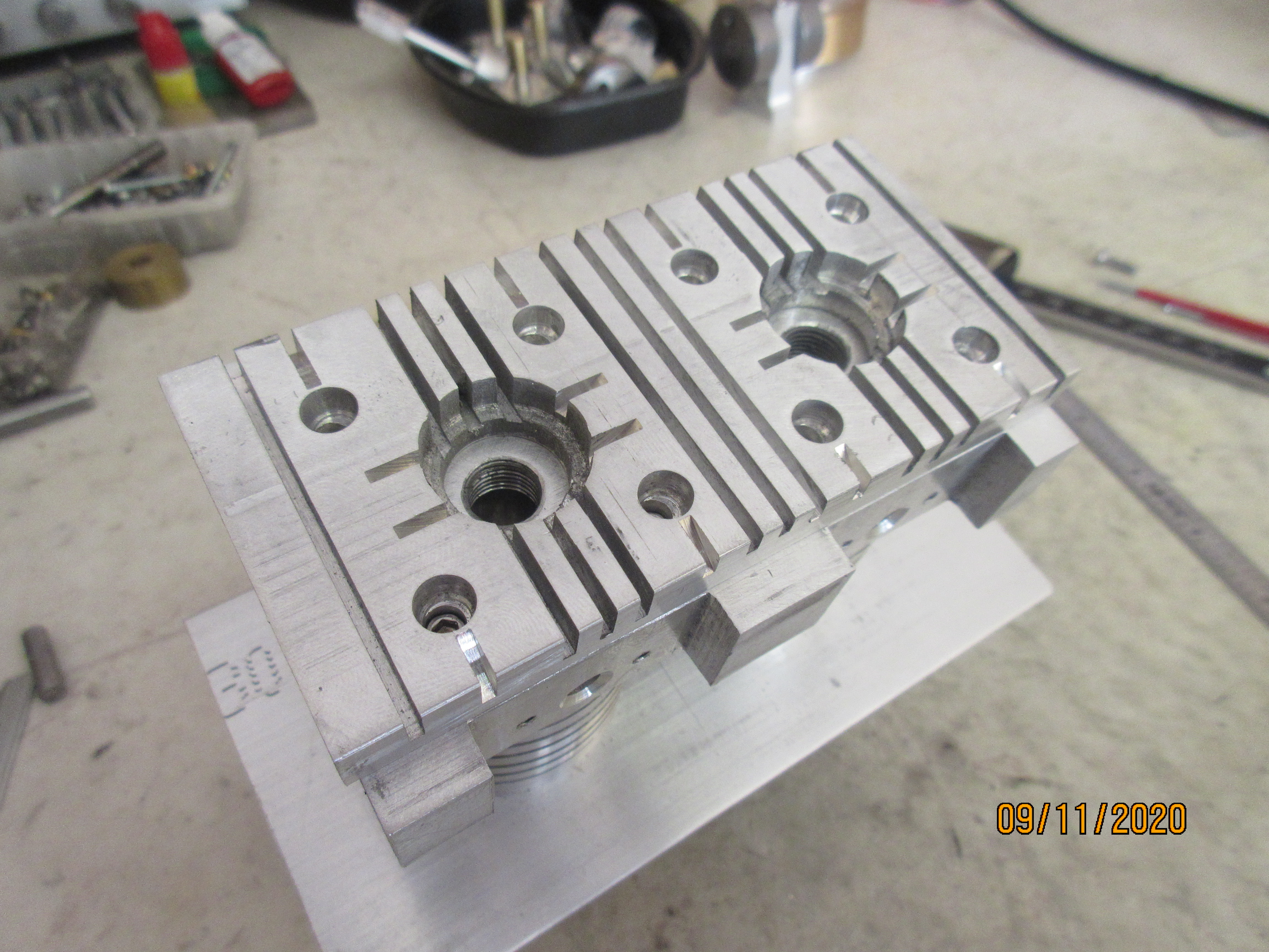
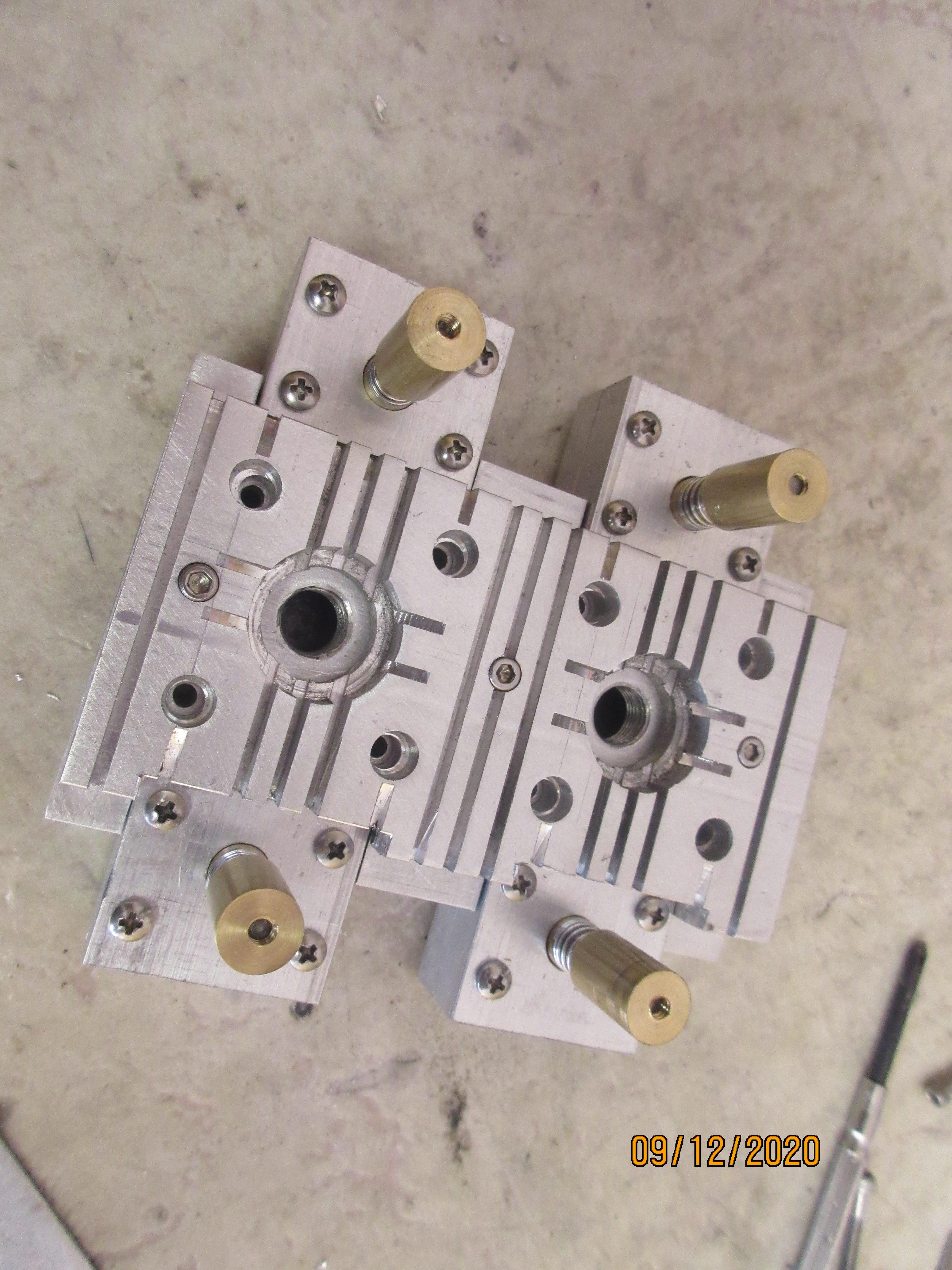
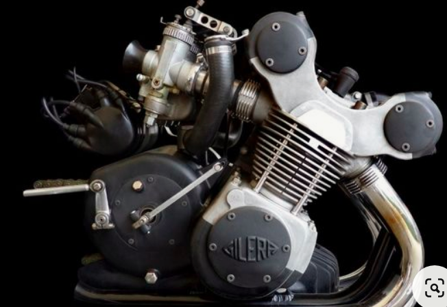
I've taken one of these and put it into the Longboy Engine smelter......
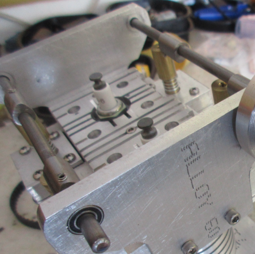
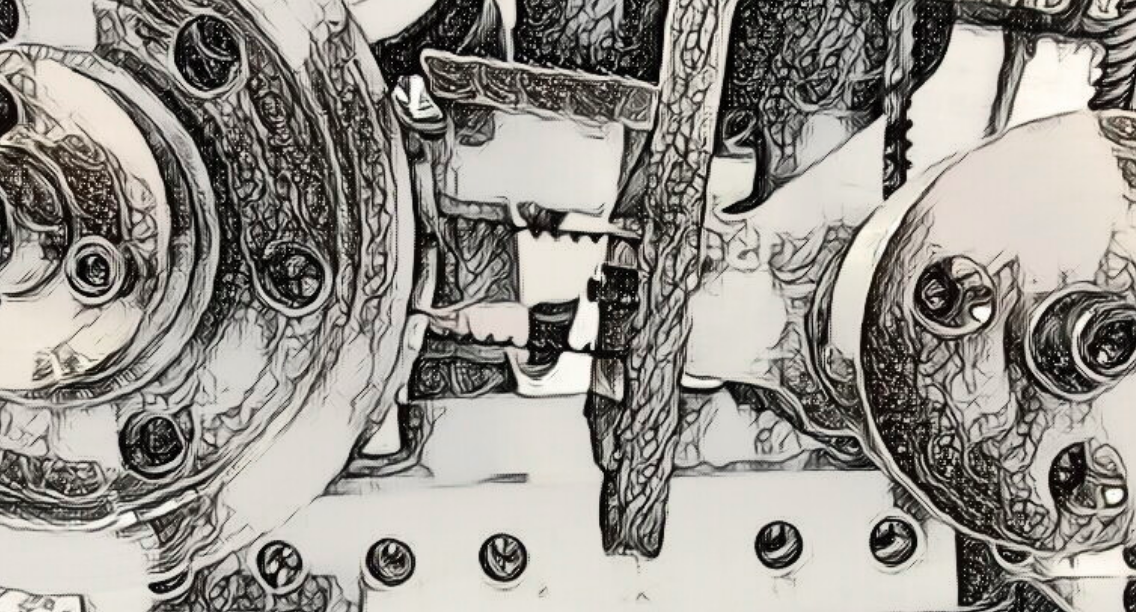
........then I added one of these into the smelter.
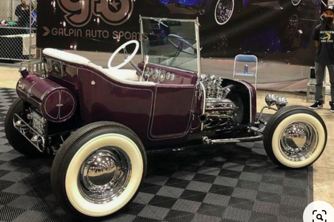
Then I started to pour the combination into the mold of the mind! The WEDGE RUNNER STORY coming this weekend!
So I begin with a concept.
I've taken one of these and put it into the Longboy Engine smelter......
........then I added one of these into the smelter.
Then I started to pour the combination into the mold of the mind! The WEDGE RUNNER STORY coming this weekend!