Thumper--a 1 3/8" bore i.c. engine

Home Model Engine Machinist Forum

Help Support Home Model Engine Machinist Forum:

This site may earn a commission from merchant affiliate links, including eBay, Amazon, and others.
More weld left means stronger joints. You are going want to keep an eye on those welds though. There will be some flexing because of the inertia of the outer ring and it doesn't take much to start cracking a weld.
 
Hi Brian:
I bet that old dog is really wagging it's tail! Ha ! Ha ! Good job!
I was able to get out of the house yesterday but went NOWEAR!!
Bill Thomas
stuck inside in Michigan USA
 
wthomas--You made me laugh. In times like this anything that makes me laugh is very welcome!! This afternoon I finished the cleanup of the flywheel I welded this morning, then disassembled the engine for paint, and painted the flywheels, gas tank, and rocker arm support a nice green color. I get out every day around 2:00 o'clock to go for my "fat mans walk" on the forest trails across the road from my house. It's only a mile in total, but most of it is hilly.
 
Ladies and Gentlemen-I present "THUMPER" in all it's beauty. Yesterdays paint job dried overnight, and everything got unmasked and assembled this morning. Now I get to the point where "Thumper" can not stay on it's merits as being pretty---It has to actually run for me. I started this build on or about the 1st. of March, and had everything completed by the beginning of April except for the flywheel/fan blades. I had some time in April devoted to purchasing and learning to use a new Tig welder, and a few days of stomach flue. I am happy with the way this engine turned out, and will be even happier if the next stage (getting it to run) goes fairly easy on me.----Brian
b9D4hu.jpg

55lSd0.jpg

FXccxG.jpg

O1v6kn.jpg
 
Now we get to talk about cam timing. As you can see in the drawing, there is about 125 degrees of "cam influence". That gets doubled when you think of what is happening at the crankshaft, because of the 1:2 ratio between the crankshaft gear and the camshaft gear. So---at the crankshaft we have 250 degrees which we have to account for. When the piston travels full stroke from top dead center to bottom dead center, that accounts for 180 degrees. so 250-180=70 degrees. I like to have the intake valve start to open about 20 degrees before the piston reaches top dead center on the exhaust stroke. I can adjust the cam position to make this happen. If we take that 70 degree figure and subtract the 20 degrees from it, then that means that the intake valve will close 50 degrees into the compression stroke.--I can't set that last figure. That last figure is totally dependent on the shape of the cam. I like my exhaust valve to begin opening at 45 degrees before bottom dead center on the power stroke, and I can set that. So, again, if you subtract that 45 degrees from 70 degrees, that means that the exhaust valve stays open until 25 degrees into the intake stroke. I will set the cams up as written in the text, and see what happens. These calculations do not take valve lash into account, but they seem to work for me when the valve lash is set to about 0.010".
EwAe9U.jpg
 
A very hansom engine. Looks like it means business. :)
As for cam timing you can always leave a bit more lash if you're not happy with the open and close positions.
 
Enjoyed your build very much. Especially the TIG experience. I never learned to weld.
So I always find a way around it. But I know it is a powerful tool, perhaps one day.
Your engine reminds me of the OLD mac truck Dog figure, Squat and powerful.
Thanks for sharing, Thanks for taking the time to share.
 
This morning I'm setting valve timing. There is a lot going on in this picture. On the far side of the engine is a cardboard protractor I made up. It has a wood base and a clearance hole thru it for the crankshaft. It has the degree marks that I want to set my valves to printed on it---20 degrees before top dead center and 45 degrees after bottom dead center. There is a temporary metal stand made up for my dial indicator, and the end of the indicator is setting on top of the intake valve rocker arm. I think I have a Canadian two dollar coin in there for a spacer because I couldn't get the dial indicator quite low enough without modifying the temporary stand. For the intake I have found and marked the flywheel at top dead center, then turned the crankshaft backwards until the top dead center mark on the flywheel was lined up with the 20 degree before top dead center mark on the protractor.(grub screws in intake cam and both gears are locked to camshaft and crankshaft. Then I loosen off the grub screws in the crankshaft gear and turn the camshaft gear in the correct direction until I see the dial indicator start to move. I then lock the crankshaft gear grub screws and the intake valve is set. The exhaust valve is more difficult, because the cam and crank gears are locked in position. I set the crankshaft in a position that is 45 degrees before the piston reaches bottom dead center. I loosen of the grub screws in the exhaust cam and set the dial indicator up on the exhaust valve. Then without moving crankshaft or camshaft, I have to reach in thru the "window" and spin the exhaust cam in the correct direction until it contacts the lifter. (This is far easier said than done). then the grubscrews in the exhaust cam are locked up.
UHeQTj.jpg
 
I thought I had mentioned this in my previous post, but I see that I didn't. What I did this morning does not take into account any valve lash. I set my valve lash for 0.010" after the cams are located and locked in place. In reality, the valve lash means that the cam has to turn a very little bit more than perfect design parameters before the valve starts to lift.
 
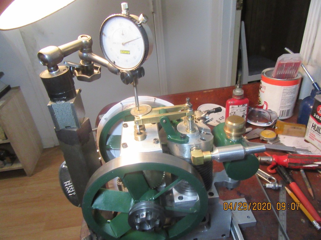
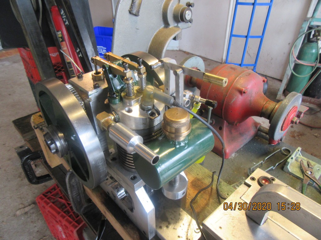
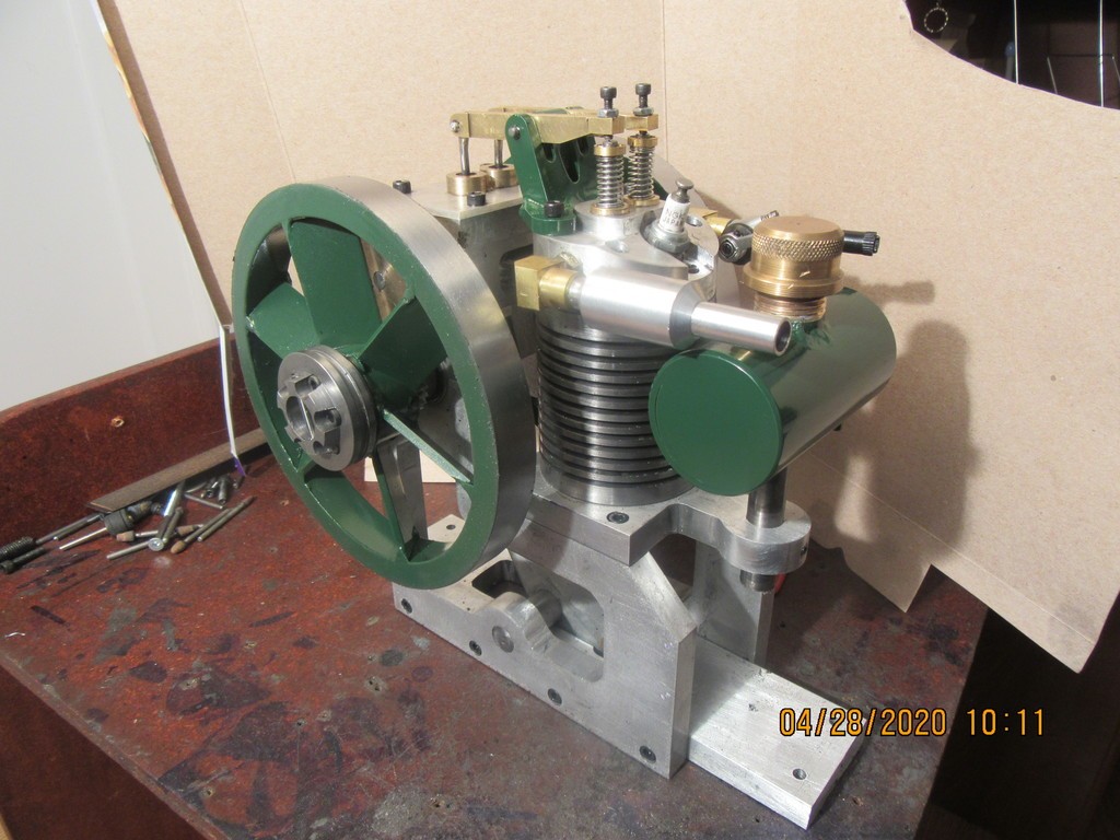
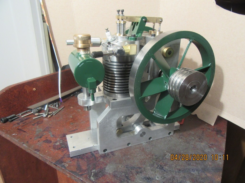
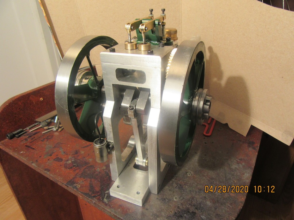
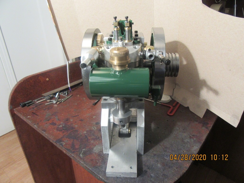
YES!!!--The engine runs. It had fairly weak compression to begin with, gave a lot of pops and farts, but didn't want to run on it's own. I advanced the timing about 10 degrees, but no joy. Everything was set to "optimum" but it didn't want to keep running on it's own. I have a new (used)1/4 horsepower electric motor that I bought a couple of months ago. I set it up and ran a v-belt from one of the motor pulleys to the offside flywheel, turned on the switch and let the electric motor run the engine. The engine was firing right along with the motor running it. The cylinder got warm and the exhaust was warm, so I just let it run. I knew that with combustion happening, the valves would begin to seal better and the rings would seat. After about 15 minutes I stopped everything, took the belt off, and started the engine the normal way, with my electric drill. I am very pleased, the engine is a runner. Now it's just a matter of taming it a bit to get a good idle and throttle response. Now that I know the engine runs okay, I will sell the plans for $25 Canadian---contact me by email. I haven't been able to get Youtube to work for me for the last month or so, but tomorrow I will get a video of it with my camera and see if my wife can open a new account on Youtube. If she can't I'm going to have to figure out another way of getting a video to post.---Brian
 
Hurray! This is a unique engine, and I look forward to seeing all that crankshaft action in motion!

Congratulations Brian, and I’m keeping my fingers crossed that you’ll solve your YouTube problems.

John
 
If I have one complaint about Traxxas 4033 carburetors, it's this. If you don't have some over-riding control on the throttle, then as soon as your engine starts it will open the throttle wide open. The only way I have found to get around that is to make up my own throttle lever with a good heavy compression spring at the pivot point and a lever connecting it to the Traxxas throttle lever. That way the engine stays at whatever throttle setting you choose. It is very exciting to have your brand new engine start and immediately rev up to the point where you are afraid it may explode before you get the ignition switch shut off.
MF4YT0.jpg
 

Latest posts

Back
Top