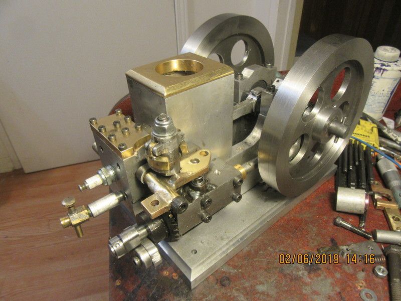
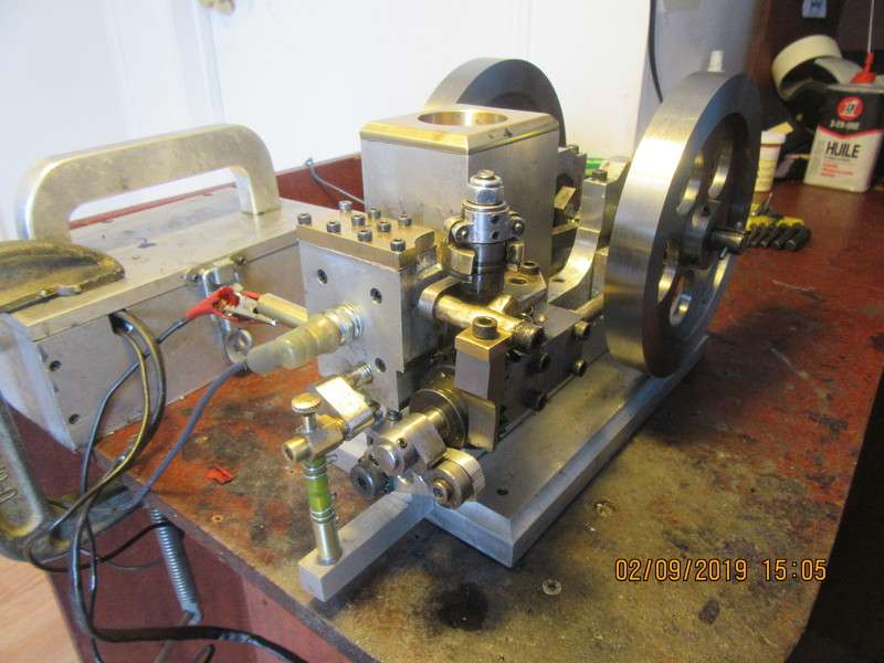
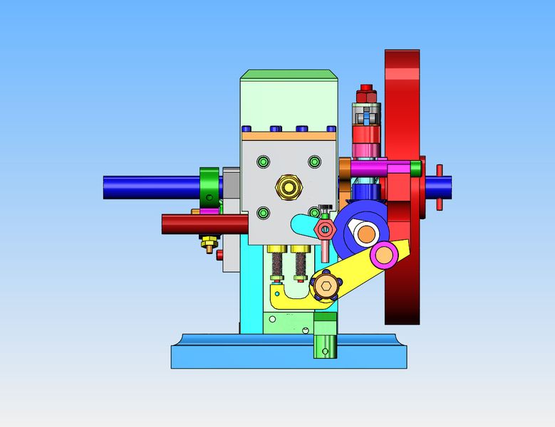
Check this out. This is so cool!!! I have replaced the face cam with a more conventionally shaped cam, and added a really strange rocker arm. I love it when the real parts operate just like my cad program said they would. There was nothing wrong with the face cam I had on the engine originally, but there were problems involving consistent latching of the exhaust valve lockout mechanism from the governor. In order to change this (and hopefully improve it), I had to change the style of cam I was using.

You are using an out of date browser. It may not display this or other websites correctly.
You should upgrade or use an alternative browser.
You should upgrade or use an alternative browser.
Design and build side-shaft hit and miss engine from bar stock
- Thread starter Brian Rupnow
- Start date


Help Support Home Model Engine Machinist Forum:
This site may earn a commission from merchant affiliate
links, including eBay, Amazon, and others.
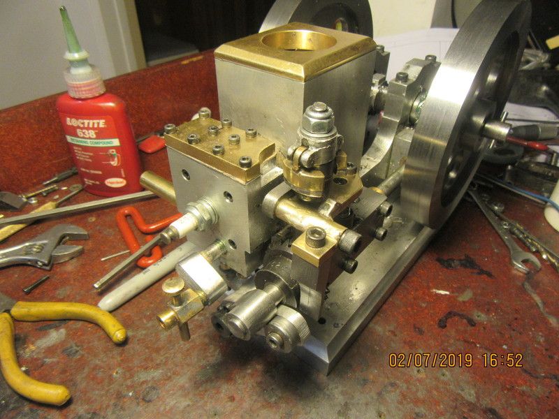
So---Here we are again. It looks almost the same as it did the last time around, but there are changes. The face cam is gone, replaced by a conventionally shaped cam, and my wonderful rocker arm as seen in the previous video. The head is completely changed, and the brass tilting part of the governor arm has had the pivot moved around to the other side of the stem post. All I have to do now is make my new lockout arm and we'll try this rodeo again!!
The more I thought about how close that carburetor was to the sparkplug, the more it bothered me. It isn't the shock that bothers me so much--It's where you move your hand to involuntarily when you get the shock. I have never been hurt by any of my engines so far, but there are a lot of things going on up at the front of this engine. I don't want to get a shock, jerk away from it, and feed my fingers into the meatgrinder. The engine has been retimed, both valve timing and ignition timing. It is ready to go except for the small manifold that bolts onto the engine to channel gasoline from the gas tank up to the carburetor. I also have to incorporate my anti-backflow valve into the manifold.
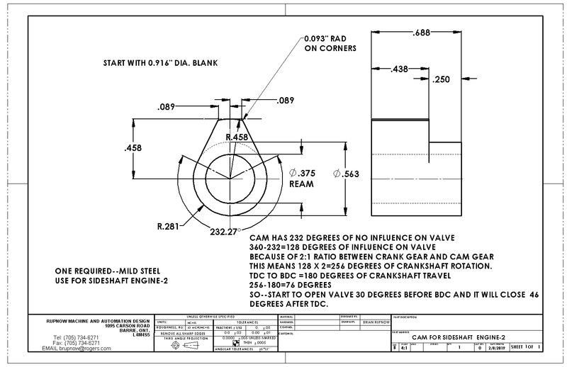
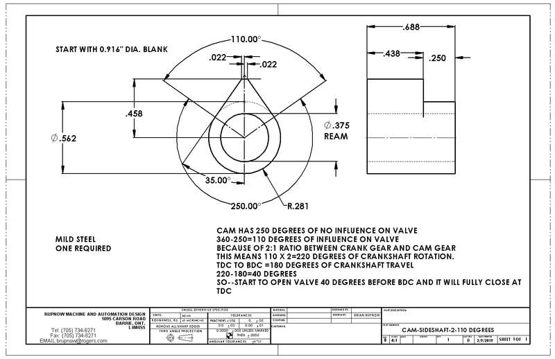
Here is an interesting fact. The face cam I made for this engine had all of the action imparted to the valve in a 90 degree segment. Because of the 1:2 ratio between the crankshaft and camshaft, that means that all of the valve movement occurred in 180 degrees. The engine ran, and seemed to run relatively well. The new cam, which is patterned after the Odds and Ends hit and miss engine by Philip Duclos has 128 degrees of cam influence, which results in a whopping 256 degrees of crankshaft rotation. Since there are only 180 degrees of crankshaft rotation as the piston moves from bottom dead center to top dead center on the exhaust stroke, that means that the remaining 76 degrees has to be used up before and after the piston is at bottom dead center and then at top dead center. This is normal on internal combustion engines, and is highly theoretical, because when you take the clearance between the rocker arm and the end of the valve stem into consideration, the "lead" and "lag" of the valve action isn't as much as the theoretical numbers would have you believe. Hit and miss engines are not a high revving engine, so it probably won't make as big a difference, but it will be interesting to see.
Last edited:
Today I made the last piece for this engine, and what a snaky piece it it!!! This is the manifold that connects to the base of the cooling reservoir and forms a leakproof seal with the extended tube from the gas tank, and channels fuel through it's many galleries to the anti backflow valve and then to the carburetor. There will be a piece of transparent fuel line connecting the anti-backflow fitting to the carburetor, which allows me to see what's going on with the fuel. Right now the piece has half a dozen brass plugs held in place with J.B. weld, and after it sets up overnight I will add it to the machine and see if it runs.
Good news--Engine is firing consistently when spun by drill, which eases my mind somewhat about having enough compression to fire with the new head on. (The new head has a larger combustion chamber than the old head had.) Since I also had to make new valve cages for the new cylinder head, (couldn't re-use the old ones) I was concerned about the valves sealing but it seems they are going to seal all right. --The old valves were installed and lapped into the new seats through that access hatch in the top of the cylinder head. Flywheels will bounce back when spun by hand against compression. I have hurt my back, so I'm trying not to do too much for a few days, but I had to try this new configuration out to see what was going to happen. When I had the cylinder head off, I measured the distance from the head of the piston to the end of the cylinder at top dead center, and I have about 0.176" there. If I have to, I can add that much to the top of the piston to bring the compression ratio higher. This is probably all for today, but it's looking quite good so far.---Brian
Last edited:
nel2lar
Well-Known Member
Brian
I think it is VERY COOL. Nice job working something special out.
Good job
Nelson
I think it is VERY COOL. Nice job working something special out.
Good job
Nelson
Hi Nelson. I did alter the cam profile this afternoon, on the advice of George Britnell. George is very knowledgeable about design and construction of small engines. I have the engine firing consistently, but not quite to the point where it will take off and run on it's own without the variable speed drill I use as a starter. I have spark, I have fuel, and I have the ignition and valve timing correct. The two things left which would cause the engine to not start are #1--Too much friction as the engine is still quite "stiff" because it is new, and #2-there is a lot more room inside the cylinder head now, which gives lower compression than in the previous design. I have room to add 0.200" to the end of the piston to increase the overall compression, and since that is the easiest thing to do I may do that tomorrow. as far as "stiffness" of the engine, I can always oil everything up good and then drive the engine with a v-belt from my 1/2 HP. electric motor for a couple of hours.
So--If we want the engine compression to come up higher, we can make the cavity in the cylinder head smaller---OR--we can make the piston longer. In my situation it was much easier to make the piston longer. Using information from my CAD system, I determined how much longer it could be, and what diameter it had to have. The diameter had to be a tiny bit smaller than the actual piston size, because the piston was already designed and lapped as a "precision fit" in the cylinder. I assembled the lengthened piston to the rod and the rod to the crankshaft and turned the engine over by hand to be sure nothing interfered. Nothing did, so I pulled it apart again, put a dab of J.B.Quickweld on the threads of each bolt and reassembled the lengthened piston. Now I'm off to get some lunch, and by the time I'm finished eating, everything will be ready to go back together.
nel2lar
Well-Known Member
Victory is in sight. I believe you got it.
Nelson
Nelson
- Joined
- Sep 19, 2015
- Messages
- 274
- Reaction score
- 80
G,day Brian. I find what you have done with your piston very interesting. On low speed engines like these a two piece piston design may be an excellent way of experimenting
with different compression's with an added bonus of the wist pin never accidentally moving and scoring the bore .
Cheers
John
with different compression's with an added bonus of the wist pin never accidentally moving and scoring the bore .
Cheers
John
Hi John--I've had a frustrating day today. I have removed/fixed all the things that would keep the engine from running, and it still doesn't want to run on it's own. I have one more trick to try, and if it doesn't run then it's going up on the workbench to be driven by my 1/2 horsepower electric motor until any residual "stiffness" goes away.
While learning more about the engine, I changed the combustion chamber by changing the connecting rod (making it longer or shorter) And now I have seen my stupid  .
.
Thanks Brian !!
.Thanks Brian !!
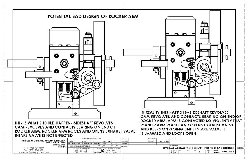
I'm not having a lot of luck here. I played all day yesterday, doing all the usual tricks to get a engine started. Valve timing, ignition timing, carburetor settings. I even set the engine up in my main garage and ran it with a 110 volt electric motor for a couple of hours to get rid of any tight spots. No Joy!! Engine fires right up and runs along with the starter drill, but doesn't want to keep going on it's own. I am having an issue with the intake valve seizing open. I have never had that happen before, so I've been theorizing as to why this is happening. I think that there is a flaw in the design of the rocker arm, and that "at speed" the rocker arm which should only move the exhaust valve is being "flung" out so hard by the cam that it is over-travelling and hitting the intake valve. That is my current reasoning, so today I will investigate the rocker arm design. Will also do a bit of research and calculate the engines current compression ratio.
- Joined
- May 15, 2017
- Messages
- 481
- Reaction score
- 298
Hi Brian. To test your theory how about a temporary tension spring on the valve end of the rocker to control the bounce.
I spent the best part of this morning redesigning the rocker arm so it gives a lot more clearance to the intake valve. While I was deeply into the design, I noticed that the length and positioning of the arm which has the cam follower on it was not correct. I'm not certain how that happened, but it did. I will now embark on making a new rocker arm and cam follower arm. S&*t happens!!---and Tony M--I thought of that, and it may still happen.--Brian
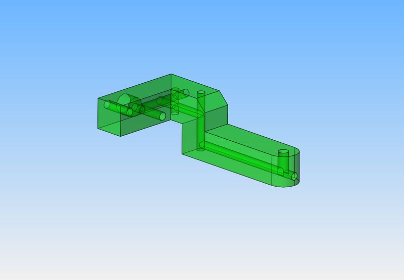
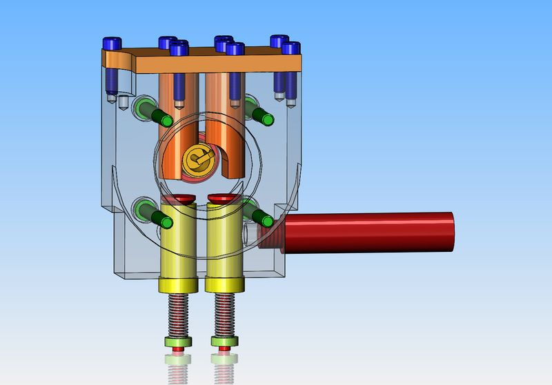
Here is an interesting model of the cylinder head I have designed and machined. The two holes that extend up to the bolted cap plate are machined into the body of the cylinder head to allow insertion of the valves. In my original design, the two orange colored dowels were simply there to fill up the holes and cut down on the amount of "free space" in the burn chamber. Now that I've had time to play with the engine a bit, the thought occurred to me---"I could cut down even more of the burn chamber space if I extended the dowels to a point just clear of the valves heads when the valves were open." They would have to be machined on the end to provide clearance for the sparkplug, but that poses no difficulty.---Brian
nel2lar
Well-Known Member
Brian
I was looking at your diagram and my thought is to re-make the head. I know that is a too much but here is my idea. Drop the hole for the plug down with just enough clearance to not get hit by the valves. Now the big one the combustion chamber be not be the circle but a cut as a slot just wide enough to have valve clearance. The spark plug hole bored just deep enough to allow for clearance of the electrode and deep enough to prevent the spark from jumping to the metal instead of the electrode.
Was the engine running before you changed the cam and redesign?
I believe you are going to get it, hang in there.
Nelson
Nelson--You're late to the show. I have designed a new head very close to what you are suggesting, but I'm not ready to go there yet. The engine ran fine before I changed to the new head design. Did you not see the videos that I have posted links to earlier in this thread? See post #261.---Brian
The Problem as I see it is the mass of the rocker arm at the cam end out weigh the opposite end by a large amount. the pivot for the the rocker ar is too far off centre. I would shorten the rocker arm on the cam side and put the roller under the centreline of the cam shaft. The rocker on the cam shaft end should be no heavier than the valve end. I shore if you do that you will have a sweet running engine to your Satisfaction Cheers, John from JohwenI'm not having a lot of luck here. I played all day yesterday, doing all the usual tricks to get a engine started. Valve timing, ignition timing, carburetor settings. I even set the engine up in my main garage and ran it with a 110 volt electric motor for a couple of hours to get rid of any tight spots. No Joy!! Engine fires right up and runs along with the starter drill, but doesn't want to keep going on it's own. I am having an issue with the intake valve seizing open. I have never had that happen before, so I've been theorizing as to why this is happening. I think that there is a flaw in the design of the rocker arm, and that "at speed" the rocker arm which should only move the exhaust valve is being "flung" out so hard by the cam that it is over-travelling and hitting the intake valve. That is my current reasoning, so today I will investigate the rocker arm design. Will also do a bit of research and calculate the engines current compression ratio.
Similar threads
- Replies
- 148
- Views
- 22K
- Replies
- 5
- Views
- 2K
- Replies
- 27
- Views
- 3K