Double acting Double Oscillator

Home Model Engine Machinist Forum

Help Support Home Model Engine Machinist Forum:

This site may earn a commission from merchant affiliate links, including eBay, Amazon, and others.
Now that the excitement has died down a little, I have been analyzing what is happening here. The faces of the moving disc and the stationary part of the valve must fit tightly against each other at all times to prevent air loss. This is not happening. When the engine is revolving in it's original direction, there is very little air leakage at the reversing valve. However, when I swing the handle thru a 90 degree arc to run the engine in the opposite direction, there is a lot more air escaping from between the valve faces, and that is the reason the engine is running slower, contrary to what I first thought. I believe that the reason for this may be that the faces are held tightly together by a thread cut on the outer diameter of the pivot shaft and the inner diameter of the rotating disc.--I have never had a lot of luck getting a threaded connection so perfectly square to the rotational axis that the pressure is equalized all around. There are a couple of ways I can think of to make a better seal. One would be with an o-ring slot milled around the circumference of the rotary disc as shown in the attached picture. The o-ring slot would be cut to about 75% of the o-ring's cross sectional diameter, so that when the threaded sections were screwed tightly together the o-ring would be for all intents crushed flat. Then if rotated thru 90 degrees and there was any loosening of the two pieces the o-ring would expand to "fill up the gap". That is probably the solution that takes the least amount of work. A second way would be to remove any threads from the inner diameter of the rotary disc so it is free to slide on the pivot shaft, and have a longer threaded end on the pivot shaft with a small die-spring captured between the hex nut and the face of the rotary disc. I have to ponder this for a while to decide what I will do.
0OWrCa.jpg
 
Brian, you may have to lap the valve disc to the valve body, I have seen this done before and they list this as part of the fit and finish.

Cheers
Andrew
 
I'm wondering if the oring would achieve much though. It would stop air leaking direct to the atmosphere but wouldn't stop leaking air across the two ports would it? And from the way I think it works, this might cause just as big an issue wouldn't it? Just thinking aloud here...
 
Lovely engine Brian.

I agree with Cogsy that the o-ring idea is not a good solution. I would lightly spring load the disc. You just need enough spring pressure to counteract the load caused by the air pressure on the disc. You could then give a bit more clearance to the shaft to allow for any slight misalignment.
 
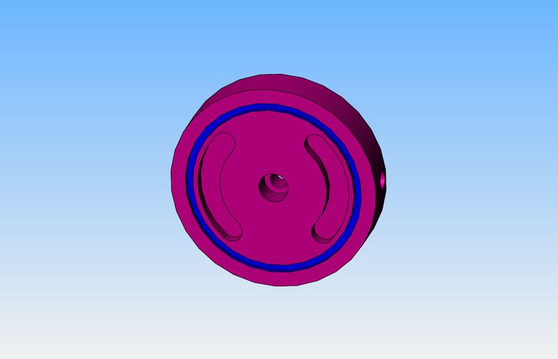
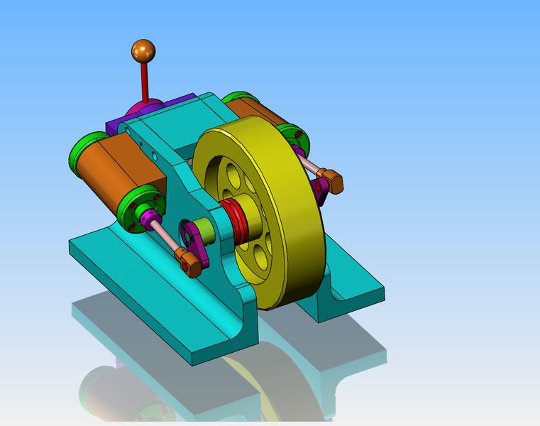
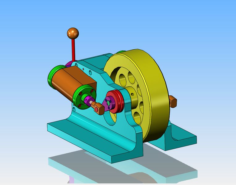
Okay Guys---Good advice. I drilled the threads out of the rotary disc, and opened up the 1/4" diameter that was a "precision fit" on the 1/4" pivot shaft x about .005" . I found a couple of little compression springs and captured them under the hex nut so they bear against the front side of the rotary disc. This is going to work, and quite well I think. It still leaks a bit around the edges of the disc, but it's dramatically reduced.--And--If I apply a little more pressure with my thumbs on the face of the disc, the air leakage totally stops. I will go down to the company where I buy my springs and pick a heavier compression spring this morning. The compression springs I have on hand are a bit wimpy, but are strong enough that I believe this operation is going to be a success. thank you for the advice and suggestions.---Brian
 
Just got back from my spring people with a very stiff little compression spring and installed it under the hex nut. The air leak is completely gone.---And yes, it runs the same speed in both forward and reverse. The new spring is 0.040" diameter wire x .3125" outside diameter with a 0.050" pitch when free and a free length of 1.1". In it's fully compressed state it is 0.350" long. Again, thank you to everyone for their help.---Brian
 
A word of caution here---People are buying plan sets for this engine, and I have been explaining to them that in it's current state there is really no good way to have a power take off from it to run anything. If people want to use a belt drive to power something using this engine, then three parts have to change. The crankshaft, spacer angle, and manifold all have to be 1/2" longer. This allows room for a 1/2" wide pulley to set beside the flywheel so the engine can be used as a power source to drive a belt. Tomorrow I will add drawings for these three items to the design package.---Brian Rupnow
 
And if you were wondering---this is the engine with the power take-off modification. Basically, what it means is that the two angles which make up the main frame of the engine are 1/2" farther apart. This gives room for the red, 1/2" wide power take off pulley.
9UGSPH.jpg
 
I have been asked by a forum member to post a video of the engine running with the new "Leakproof" reversing valve design. Here ya go---
 
Yes, a little dab of grease, not much. same as where the cylinders osscillate against the face of the frame angles.
 
Oh my god---A GIANT BRAIN FART!!!!! I spent a goodly share of yesterday designing all of the components required to widen the engine and add a take off pulley beside the flywheel. Got up this morning and looked at it and thought "I could just put the pulley on the crank arm without changing anything else". Musta been that funny stuff I was smoking yesterday---
bMYJJP.jpg
Would adding the pulley outboard put too much pressure on the crank on that side? But then, you'd have to disassemble the engine to put a belt on or take it off...
 
Chucketn--Don't forget--this is not a seriously industrial type engine. It only has a 3/8" diameter crankshaft. A 1/8" rubber o-ring drive belt would never put as much strain on the crankshaft as the cylinder which is even farther outboard than the pulley.
 
Thanks for posting this interesting project Brian. Initially I wondered if putting the pulley outboard of the frame would mess up the cylinder / piston alignment then looked back at the previous drawing. Where I see that you have simply replaced the original spacer with the pulley a nice, simple solution. Amazing what walking away (or in your case a night's sleep) and looking again triggers in the old grey matter isn't it?
Thanks again,
John B
 
Now that the reversing valve is working, I was wondering if you might go back and look at valve tweaks that could make it also a throttle, like you noted in a previous video. That would really make it a complete package.
 
No, I won't be doing that. I can regulate speed by turning down air pressure at the regulator, or by running at full (80 psi) pressure and running it thru a needle valve to regulate volume.
 

Latest posts

Back
Top