Hubbard Marine Engine

Home Model Engine Machinist Forum

Help Support Home Model Engine Machinist Forum:

This site may earn a commission from merchant affiliate links, including eBay, Amazon, and others.
Joined
Sep 6, 2007
Messages
1,275
Reaction score
322
Location
Skibbereen, West Cork
For a long time I have considered building the Hubbard 2 stroke marine engine from castings available from Heinz Kornmuller http://www.classic-motors.at/modellmotoren/modelengines.htm

The fact I have not seen any build articles going all the way to completion, and also only one You Tube video all helped me resist temptation. There must have been quite a number of casting kits sold around the world; surely there must be more than one model completed?

On this forum, I’ve found only 2 references to this engine:
http://www.homemodelenginemachinist.com/showthread.php?t=20591&highlight=hubbard
http://www.homemodelenginemachinist.com/showthread.php?t=20772&highlight=hubbard

Brian Rupnow rekindled my interest with his very interesting build of a 2 stroke engine based on the Hubbard. I waited until Brian had got a working model and then decided to take the plunge and spend the kids’ inheritance - all 191 EU - on a set of castings.

During Brian’s build saga, I started looking for information on the full size engine. There’s not much out there, but I did stumble on a volunteer helper at Mystic Seaport http://www.mysticseaport.org/ and he has helped me a lot with pictures of engines and answered many queries. Thank you, Nate.

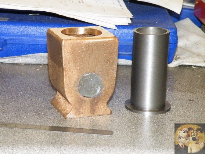
The castings duly arrived and looked good and clean.

1 Castings.jpg

The drawings came on a CD to be printed by the user and are very well detailed in both Metric and Imperial measurements (using exact conversion), but the engine if produced to the drawings would be very basic so I am attempting to make a few embellishments to get the engine looking closer to the ‘Real Thing’.
Things that I noticed on the full size engines:
A priming cup was fitted to the cylinder head.
There is a cooling water drain on the side of the cylinder jacket.
The crankshaft was greased by external oilers – one on each crankshaft housing and one in front of the flywheel for the crank pin.
The flywheel incorporates a starting handle.
There is a crankcase drain.
The cylinder oiler has 2 drip feeds, although I can’t find out what the second one is for and anyway, my skills are not good enough to make this type in such a small scale.
The model carburettor bears no relationship to the original Schebler item. Looking at the construction of these in full size, there is no way to reproduce it in 1/5th scale.
As time goes on, there may be some other additions.

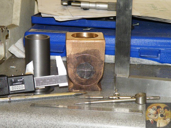
On measuring up, the castings have almost no machining allowance: definitely no room for error in setting up. The diameter of the cylinder jacket is undersize and the crankshaft brackets are undersize on length and diameter. It seems like the drawings are a guide to making the model and should not be trusted implicitly.

Dave
The Emerald Isle
 
I have made a bit of progress on the engine before writing this because otherwise there would be long gaps between postings.

Now to tackle the main casting. First up was to determine the centre of the crankshaft hole. I got a piece of aluminium and made 2 plugs that were a tight push fit in the cast holes after filing bits of flash off to get them as round as I could by eye. A drop of super glue as well as the push fit ensured they stayed put.

With a pair of jenny callipers I found the centre of the future hole. The curved end of the callipers hooked onto the rim and the point scribed an arc. This done in several places gave a good indication of where the centre should be.

2 Crankcase plugged.jpg

Standing the casting on its head and checking that it was upright, using shims as required, I scribed a line through the centre on each side of the casting.

3 Centreline marked .jpg

There is no easy way to hold this casting, so with future operations in mind I mounted the casting on a pair of 2-4-6 blocks to machine the underside of the mounting lugs. The height gauge was used to ensure both centre lines were at the same height using shims as required, the mounting lugs were machined flat. I was now able to easily hold the casting steady and true for further operations.

4 Mounting lugs.jpg

The casting was now held the right way up on parallels in the machine vice and the bore was worked on. I interposed card between the vice jaws and casting faces to help resist movement and absorb slight inaccuracies in the casting. Firstly the top was flycut and then the bore was tackled with the boring head.

5 Fly cut cylinder top.jpg

The bore has two diameters - the main bore and a small step for the liner to sit on. The liner will have a healthy dollop of Loctite 574 gasket compound to seal it, hopefully to prevent water leaking in and fuel leaking out.

Dave
The Emerald Isle
 

Attachments

  • 6 Boring cylinder.jpg
    6 Boring cylinder.jpg
    36.8 KB · Views: 1,519
I had intended to build this engine from classic-motors castings
but then i changed my mind and bought castings for De Dion engine.
Anyway keep us informed on your progress.
 
Good progress Dave.

If ever you have to block up a hole to find centre again, I used to use a sheet of lead to do it, just tap it around the periphery with a small hammer until it automatically wedges itself into the hole, then you are ready to go.

I can't remember what bit I used it on but I should have a piccy somewhere showing the method.

NB.

I remember now, it comes from my Scott flamelicker build.

Lead tapped into hole

SCOTT93.jpg


Finding centre so that it can be marked out

SCOTT94.jpg


Also note the digital measure turned into an accurate edge following scriber, an idea shown to me by John Stevenson, and it is a great for a scale that has worn out or damaged tips.


John
 
Last edited:
Finding centre so that it can be marked out

SCOTT94.jpg


Also note the digital measure turned into an accurate edge following scriber, an idea shown to me by John Stevenson, and it is a great for a scale that has worn out or damaged tips.


John

John

I like that idea of modifying the blades of calipers.

Dave
The Emerald Isle
 
There is a protuberance on the bottom of the casting that I suppose is there as a chucking piece, but for what purpose, I cannot think. So, the first enhancement was the fitting of a (dummy) crankcase drain. Full size, this was a plate screwed onto the bottom and a drain cock fitted. The chucking piece was sawn off and the casting held in the four jaw chuck and faced off. Over to the vice and the four screw holes drilled and tapped and also the centre hole for the cock. The aluminium used for the casting is very gummy and tapping 10BA holes was very taxing - plenty of WD40 was used. The largest threads on this model are 7BA - 0.0983". Strangely, I felt more anxiety tapping this material than harder metals with these small threads.

I had to do this now because the chucking piece was too long and would not have been allowed the casting to be mounted on the lathe otherwise.

7 Crankcase drain.jpg

To machine the crankcase, the casting was set up in the lathe using a centre held in a collet and another centre in the tailstock bearing on the previously marked centre dots to ensure it was level front to back. Shims were used on top of the wedge blocks so that the height setting was maintained when the holding down bolts were tightened.

8 Crankcase boring 1.jpg

When all was ready, drills were used in increasing sizes until I could easily get the boring head in the hole. It was just a matter of then increasing the bore until the correct size was reached. Doing it this way ensured both sides would be the same size, regardless of any out-of- truth in the lathe.

9 Crankcase boring 3.jpg

Dave
The Emerald Isle
 
Dave--I'm happy to see that somebody is building this engine, just so I can see all the steps required. My engine works very well, however that carburetor with the check ball in it seems to want to run at one speed and that's it. You can gain/lose a few rpm by fiddling with the spark timing, but not much. That engine is rather special to me, because it is the first time I fully lapped a piston into the cylinder with diamond compound and ended up with fantastic compression with no rings on the piston at all. That was a first for me. Good luck with your build, I will be following.---Brian
 
Hi Dave

It's good to see you working on a new project; I will enjoy following along with your progress.

Dave
 
Comming on well Dave,

I can only think the chucking spigot was there so you could bore the cylinder and face it off as the first operation and then set everything else out from that.

Then from lathe to rotary table set vertically and skimmed the underside of the mounting lugs and bored for the crank all while held by the spigot.


J
 
After the bore was done, the first crankshaft bracket face was machined using the boring head as a fly cutter. Not a lot of room between the mounting lugs on the back swing with the tool wound out!

10 Crankcase flange 1.jpg

It was over to the mill and resting the previously machined flange on parallels, the second face was cleaned up. I used a piece of 5/8" HSS to act as a spacer between the side of the vice and the machined bottom of the crankcase. A quick check with a DTI on the top of the cylinder showed it was good enough for me. The casting was now true to the mill table X axis for future work. The head end had been chocked up so that the single strap clamp held everything secure.

11 Crankcase flange 2.jpg

With both faces machined, the various bosses on the front of the cylinder could be faced off. Found an omission in the drawings - the small round blob just above the clamp is not shown! Fortunately it is not a problem because the part that screws into it can be adjusted to suit. Like I said earlier, the drawings should be treated as a guide.

The bosses were then drilled and tapped. From the top, there are 2x 10BA, 2x 9BA and 2x 8BA The round boss will be 8BA.

13 Cylinder bosses drill tap 1.jpg

Dave
The Emerald Isle
 
The model uses glow plug ignition but the glow plug is rather out of scale. What I did was to machine the hex of the plug down by 15 thou. on each face. The round part below the hex was also reduced in diameter. Hopefully the plug will still work. The design has the glow plug screwing straight into the cylinder casing, but here again I'm trying to get closer to full size and have made a plate that will screw onto the ignitor boss. The plug will slip in the central hole and with a bit of luck when screwed tight, I will still have a seal.

The ignitor plate is a piece of steel about 0.036" thick and this was just sawn and filed to shape after the 4 holes were drilled. Ignore the top two holes; I was trying to be clever and put one hole too close to the edge. Don't want to waste too much - these small bits always come in useful.

14 Ignitor plate 1.jpg

The drawings show the glow plug on the half way line but full size it is below, so this is what I have copied and the glow plug is 50 thou below centre. The two lock nuts have since been thinned down to be closer to prototype.

16 Ignitor plate 3.jpg

The boss on the cylinder will need to reshaped somewhat later on.


Dave
The Emerald Isle
 
Moving on down we come to the push rod bracket. This required a piece of 5 x 5 mm steel, of which I had none. A raid of the potentially useful bits yielded something that didn't take too much effort to get down to the correct cross section. The easiest way to hold it was in the side of the vice. A spare piece of the steel was used to balance the pressure of the vice jaws while the holes were drilled and the slot machined out. The part then had to be turned 90 degrees for the ignitor push rod hole.

17 Push rod brkt 1.jpg

The ignitor pushrod shown (round bar) is a convenient find from a dead printer.

18 Pushrod brkt 3.jpg

Lastly, the part was trimmed to length to give:

19 Pushrod brkt 4.jpg

Dave
The Emerald Isle
 
Dave,

I used to hate setting up small parts in my 6" milling vice until I invested in one of these.

A 1" Vertex toolmakers vice, just set it down onto parallels and use it to hold all the small parts, no more trapped fingers or bodging up some way to support them. I usually use bits of lathe tool steel as parallels for it.

Swingup44.jpg


I could even use large cutters around it.

Mine was rather cheap compared to what they cost nowadays, but if anyone needs something like this, Arc Euro sell them and they have a 10% discount offer at this time.

John
 
Now after that little light relief, it was back to the next real job: the crankshaft brackets.

They have a taper along their length so to hold them in the chuck, the thin end was padded out to get a decent grip. The chuck is a Grip-Tru, so it was quite easy to get reasonable concentricity. Man, that aluminium is gummy; lots of WD40 didn't seem to make any difference.

20 Crankshaft housing.jpg

With the register machined, the casting was reversed in the chuck and held by it to turn the taper. If I had followed the drawings, the taper should have been 5 degrees. I managed 2-1/2 degrees to keep a decent amount of metal at the front.
The housing was drilled out 9.7mm so that when temporarily fitted to the crankcase I could check the alignment before reaming.
It was pleasing to note that after turning the step in the back that I got a nice light push-in fit with both brackets in the crankcase. So it does pay off to measure twice and cut once after all!

21 Crankshaft housing 2.jpg

I did notice that using the small carbide boring bar(dry) that the quality improved considerably while machining the recess.

22 Crankshaft housing 2.jpg

Dave
The Emerald Isle
 
With the brackets ready to fit, the first one was pushed in place. Using the DRO's PCD function, it was easy to set out the 6 holes for the retaining studs. Tapping holes went through both parts and the bracket was eased out and the holes in the crankcase tapped.

25 Crankshaft housing drill tap.jpg

The metal is less than 80 thou thick so my intention was to fit lock nuts in the cavity. That was until the inevitable happened: I had either too much pressure or perhaps not enough pressure on the tap when withdrawing it and the thread stripped. Yes, locknuts are now a definite necessity! That was the first side done. The casting was unclamped and the parallels rotated to give clearance for the bosses on the front of the cylinder. Same procedure as before to line up the casting and repeat drill and tap. Well, darn me if the same thing didn't happen again and another thread came out 'rather loose'. Each housing and the crankcase was centre popped by the top hole: one pop for the front and 2 for the rear, just in case there is any discrepancy.

I now needed some studs to hold the three main bits together. Don't care what the purists might think, but I have some 7BA threaded bar that I'm going to use. Just need a quick way of getting 12 studs to the same 3/8" length easily.

How I did it:
Use any piece suitable of material- in this case a piece of HSS - in the front toolpost as a stop bar + the rear parting tool.
Move carriage towards the headstock so that the parting tool is Just clear of the chuck jaws. Lock saddle.

28 Making studs 2.jpg

Adjust topslide so that the distance between the cutting face of the parting tool and the piece of steel is 3/8".

27 Making studs 1.jpg

Put the threaded rod in the chuck and wind the cross slide in so that the stop bar makes a stop for the embryo stud and nip up the chuck.
Wind the cross slide back out and the parting tool will come into play.
Cut off stud, withdraw parting tool, wind in cross slide cleaning up cut end if necessary and pull out the material from the chuck... And so on. Takes longer to write about it than do it. 12 studs in about 5 minutes. I held the stud material directly in the chuck, but there was no damage to the threads.

29 Making studs 3.jpg

With everything ready for a trial assembly I discovered that there isn't sufficient room within the crankcase to fit locknuts; the holes are too close to the walls - not my mistake I hasten to add!
A peek inside the crankcase will show what I mean with a potential locknut alongside an inserted stud, so a quick decision determined that two-component locknuts (JB Weld) will have to be used instead.

26 Crankcase inside.jpg

After having said elsewhere that the castings were undersize, a measurement over the crankcase flats showed that after machining they are 15 thou over! I'm not going to argue with that: I need all the metal there that I can get. I'm sure no-one will notice.

The crank brackets were temporarily bolted in place and I was very pleased with myself when the 10mm drill was pushed through to check alignment, and all did indeed line up.

30 Crank brackets fitted.jpg

[FONT=&quot]The [FONT=&quot]brackets[/FONT] now needed the bushes, so these were turned up from a suitable piece of bronze that was long enough for both parts. Taking note of what Brian discovered about wear in the bushings, I made sure I used bronze instead of ordinary brass.

31 Crankshaft bush 1.jpg

32 Crankshaft bush 2.jpg

[/FONT][FONT=&quot]The two bushes were pressed into the housings using the vice. A couple of pieces of padding protected the end of the bushing and the face of the housing. I just started the press and then put a drop of Loctite 638 in the housing as a' just in case' but the press fit was quite tight, so whether the Loctite actually did anything is moot.


33 Crankshaft bush press fit.jpg


[FONT=&quot]Dave[/FONT]
[FONT=&quot][FONT=&quot]The [FONT=&quot]E[/FONT]merald Isle[/FONT][/FONT]


[/FONT]
 
The drawings show a groove in the bushes for oiling the crankshaft. Remembering Brian's wear problems with his crank bushes, I decided to follow full size practice and use proper grease cups. On the full size engine there is one on each housing and they stick up like butterfly antennae. I will put a spiral groove in the bushes stopping short of the ends and hopefully keep the crankshaft well lubricated.

The grease cups were made in 4 parts. I put a hexagon on a suitable piece of brass bar then turned down a bit on each side to form the union, the cup and cap were simple turning jobs and the stems started life as a tent peg!

34 Crankshaft lubricators.jpg

The crankshaft brackets were again temporarily fitted and the assembly held in the vice at the appropriate angle. Holes were drilled and tapped for the grease cups.

35 Crankshaft lubricator drill tap.jpg

Dave
The Emerald Isle
 
Jumping around a bit, I wanted to make a couple of small parts that form the ignition lock out. Made from 3mm steel bar, the end was threaded 10 BA and then the 12 BA pivot screw hole was drilled and tapped; the bar was turned 90 degrees so the 1mm slot could be made and the piece parted off afterwards.

Ignition lock out 1.jpg

The lever was filed up from some 1mm steel.

Completed bracket, lever and pin. A bit closer to the real shape.

Ignition lock out 2.jpg

One more little bit to make - the other part of the ignition lock out. P2.7a and P2.7b in the drawing above. This was done in similar fashion to the previous part.

Ignition lock out 3.jpg

It is now time to start work on the crankshaft. I was hoping to have some sort of counterbalance but soon realised that if I did, the crank would not go in the hole so I will have to be content with the published design!

After facing up the six faces, the holes for the round bits were drilled and reamed.

46 Crank web 2.jpg

The block was then turned 90 degrees and a rounding over mill was used to get rid of the square corners. While in one piece, I could do top and bottom on the ends but then the original piece had to be cut into two pieces for finishing off.

47 Crank web 3.jpg

The round bits had previously been turned and were press fitted into the webs using the bench vice. As with the crank bushes, I put a drop of Loctite 638 in the holes before fully pressing together. They were cross pinned afterwards; the holes being lightly countersunk to receive the piening over. I used the shanks of old Dremel wire brushes as rivets.

Here's the crank. I took the picture after I had tried it in the bushes. It was a bit tight but I'm sure it will work itself in OK. Probably better to be too tight than too loose!

48 Crankshaft.jpg

Dave
The Emerald Isle
 
Back
Top