Hi all,
I have finished rebuilding my AL320 lathe and found many 'chinese' issues along the way, so I thought I would provide some info about it. Seeing as this forum is the only place I found any worthwhile AL320 information and other people who own one.
First, the end result... before it gets dirty and messed up again
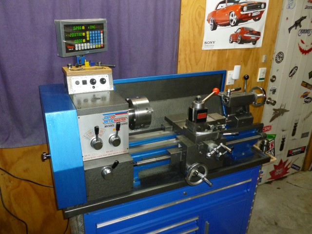
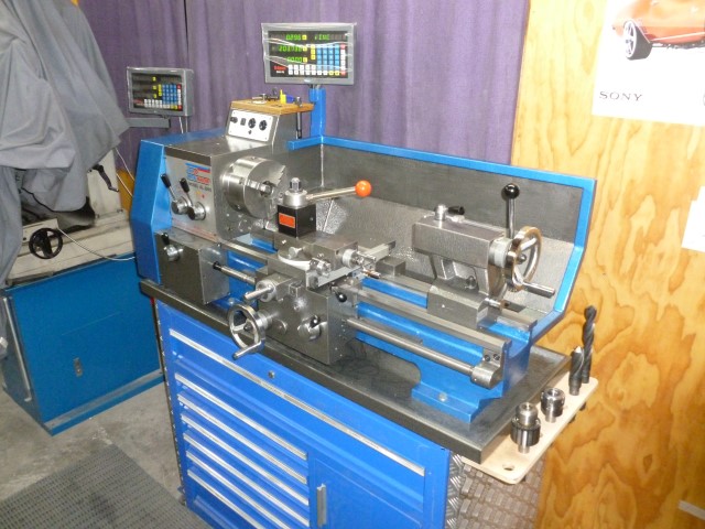
Paint is a hammer tone finish charcoal and blue
First ever mod was a tool holder and tray above the switch box
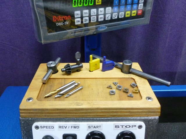
Second mod was a MT3 tool holder on the side
Originally it was 3 holders higher up on the side of the splash back panel, but I soon needed more space
Removing the half nut lever until needed I thought was a clever idea, removes risk of an accidental handle grab, and as I never cut imperial threads, I figured the dial was not relevant with my threading method
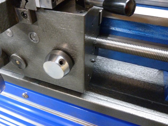
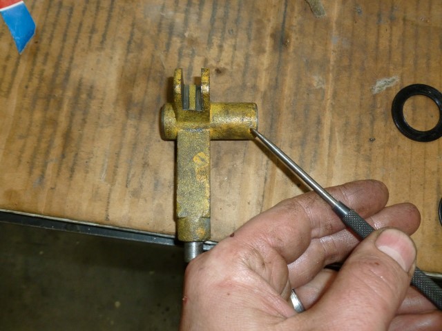
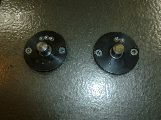
An annoying feature of this lathe was the power feed lever. It was too easy to move the lever too far past neutral, engaging the opposite feed and then crashing the tool into the work, especially when trying to finish a heavy cut or high RPM concerntration
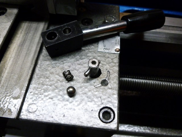
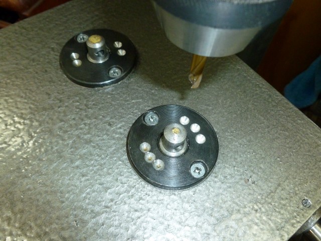
I removed the detent ball and spring from an old 1/2" power bar and installed it into the lever, moving the lever back and forth many times revealed the arc and then a spot drill hole gives a positive neutral spot
(BTW in the apron parts drawing items 43-49 is the factory detent system for this, mine was set weak from factory and adjusting tighter still gave unfavorable results, I think it's too far away from the lever)
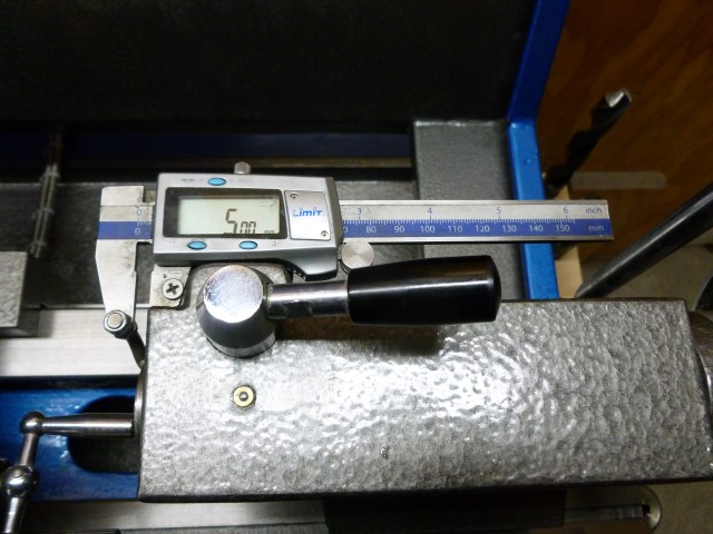
Later I Installed the digital caliper for the tailstock, if anyone paid attention to the rear dial, it counts to 69 not 70 and it doesnt count in metric
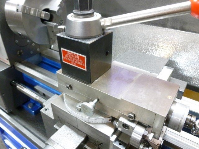
Somewhere in time the QCTP was installed, I milled the top of the compund off to lower it, I had trouble getting a good finish and rigidity during parting, surface grinding helped but I would like to make a new compund slide eventually.
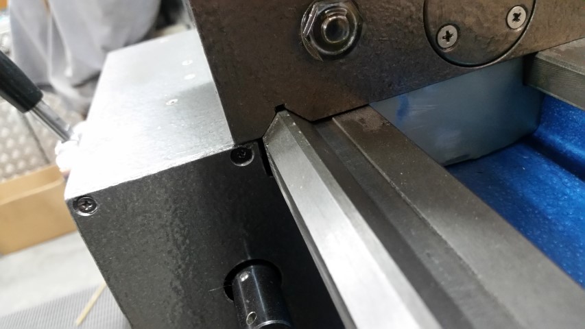
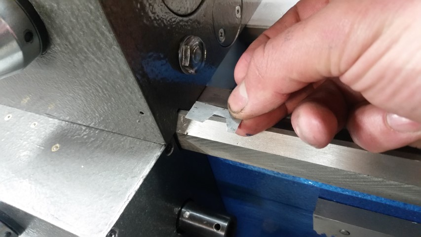
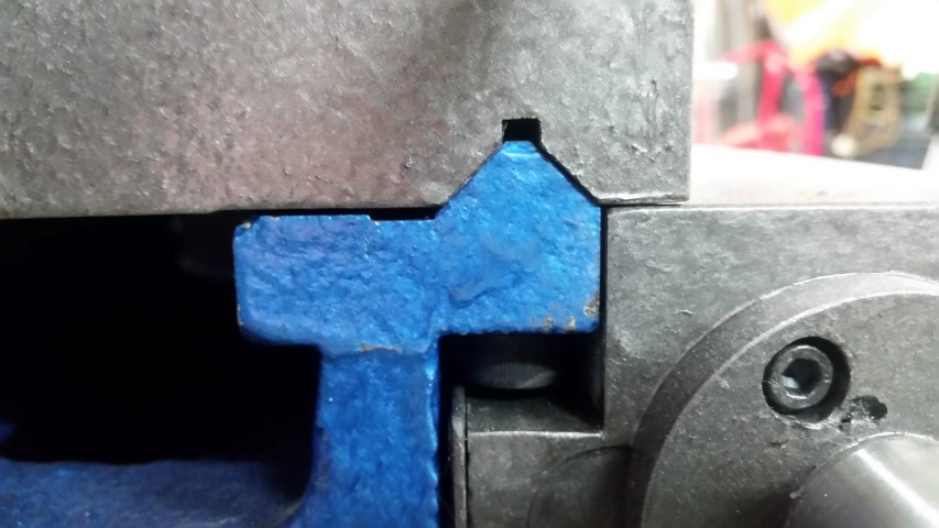
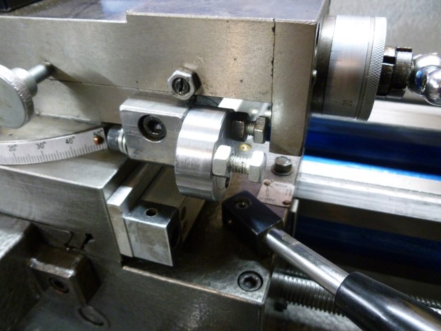
I added an end stop for the compound slide, rotatable to 3 positions
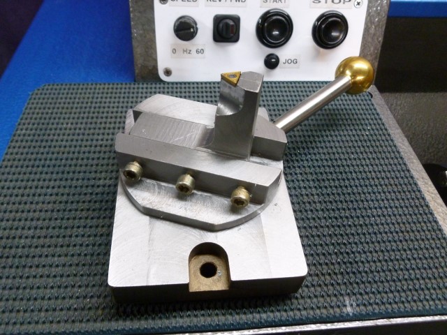
On the subject of the compound slide, removing it lets me install the ball turning tool
The DRO was installed about this time, pretty standard stuff
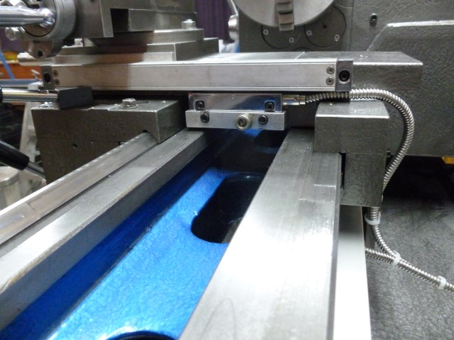
1 micron cross slide scale = 0.002mm resolution on diameter
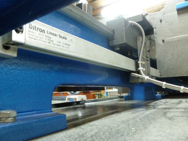
5 micron carriage scale = 0.005
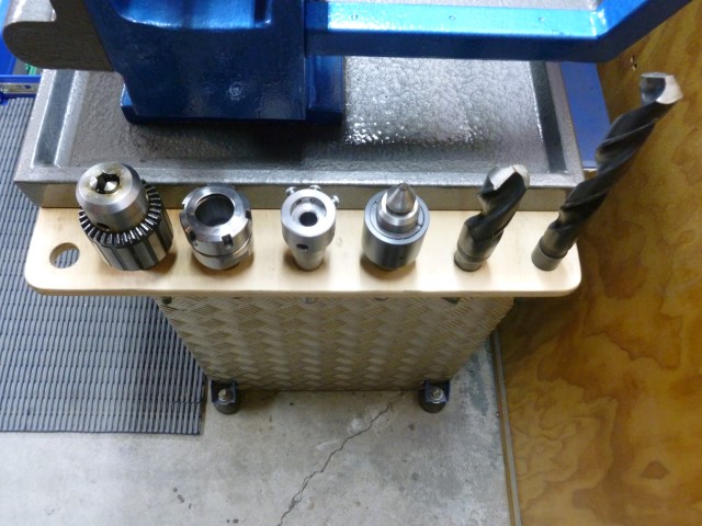
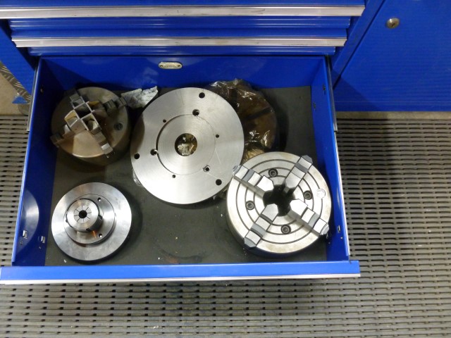
Along with the DRO, I got rid of the absolute crap stand they offer, I made a frame to hold a large Roll Cab and made use of the all the storage space...\
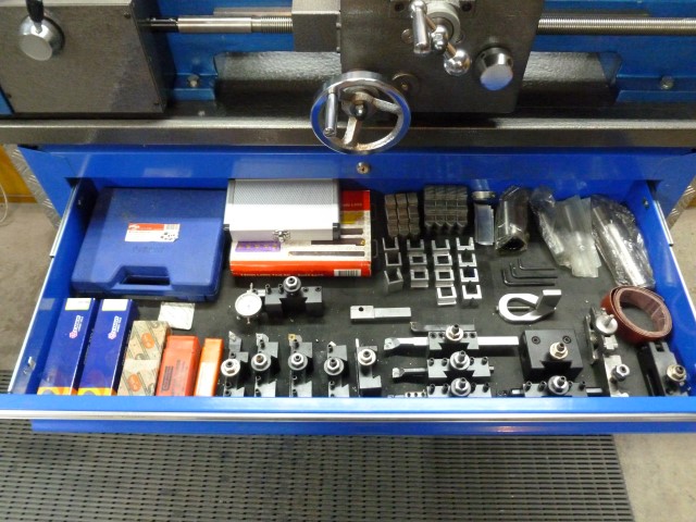
Tooling in the top drawer, Chucks in the bottom
The new base is much wider and deeper giving a better stance, removing 90% of the harmonic vibration without needing to bolt it to the floor, 4 jaw work is much better now
The best upgrade aside from the DRO and Stand is the 3 Phase motor and single phase to 3 phase VFD... ooh yeah, soft start, Instant reverse, jog button, speed dial...
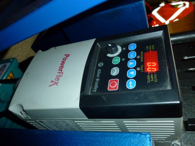
Sorry, couldn't fix rotation
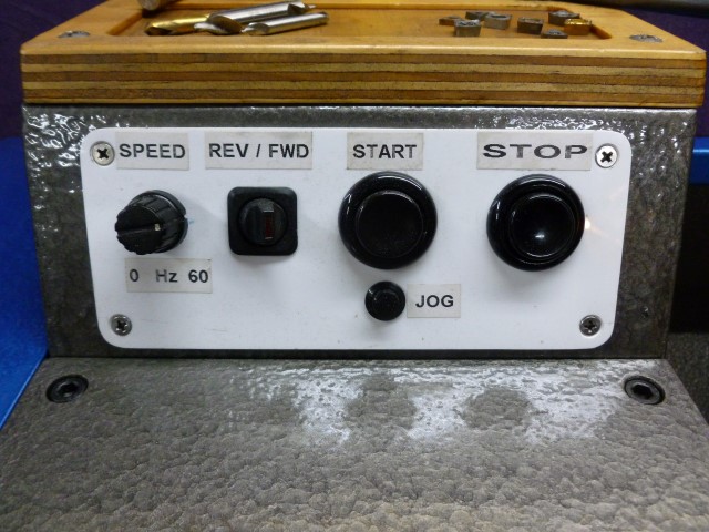
Control Box
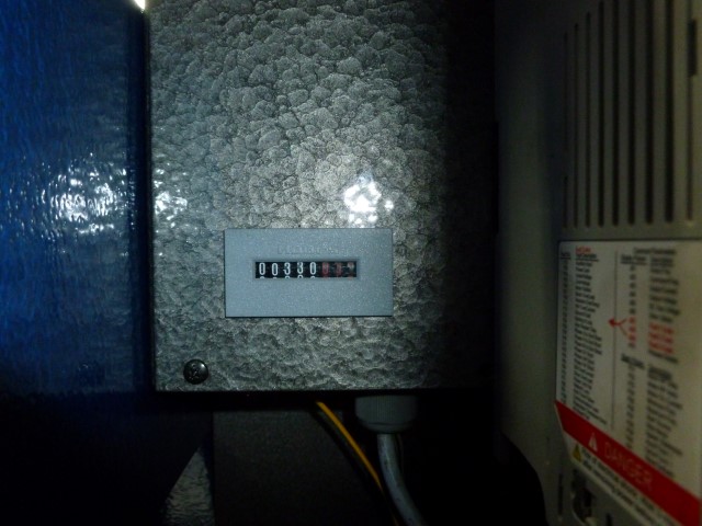
Oh and the Hour meter I installed since day 1, 330 running hours since new and counting
Lastly, the new change gear chart seeing as I removed the old one for repainting... thanks to Maryak for providing the spreadsheet here. I reformatted the sheet to merge all combinations in one block and to fit nicely on one A4 page
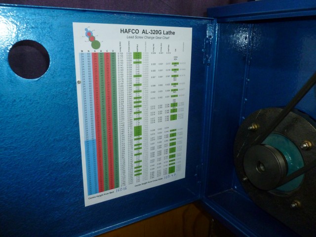
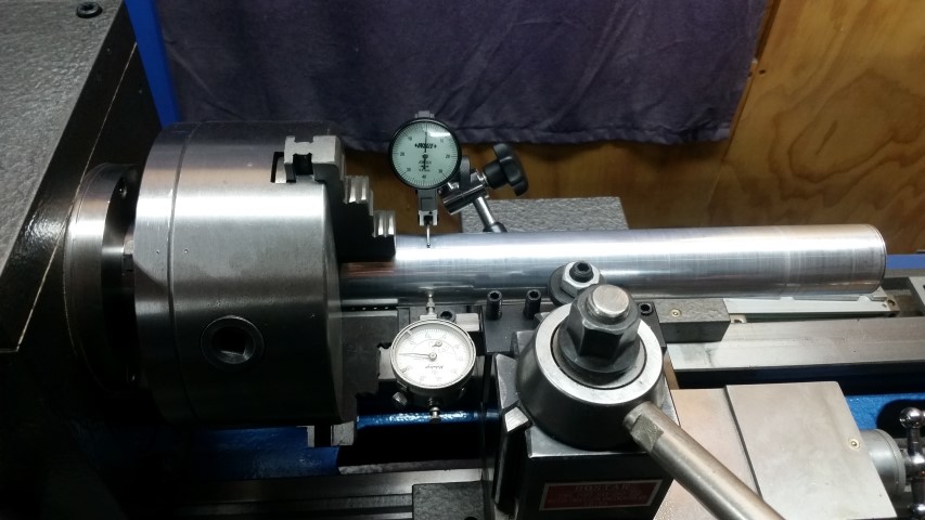
It also has a spot for the measured centre heights (@ Bed & Cross Slide)
And I will be laser printing and laminating a final copy at work tomorrow
So that's the extensive mods listed and as it sits now... I'll post some rebuild pics shortly...
I have finished rebuilding my AL320 lathe and found many 'chinese' issues along the way, so I thought I would provide some info about it. Seeing as this forum is the only place I found any worthwhile AL320 information and other people who own one.
First, the end result... before it gets dirty and messed up again
Paint is a hammer tone finish charcoal and blue
First ever mod was a tool holder and tray above the switch box
Second mod was a MT3 tool holder on the side
Originally it was 3 holders higher up on the side of the splash back panel, but I soon needed more space
Removing the half nut lever until needed I thought was a clever idea, removes risk of an accidental handle grab, and as I never cut imperial threads, I figured the dial was not relevant with my threading method
An annoying feature of this lathe was the power feed lever. It was too easy to move the lever too far past neutral, engaging the opposite feed and then crashing the tool into the work, especially when trying to finish a heavy cut or high RPM concerntration
I removed the detent ball and spring from an old 1/2" power bar and installed it into the lever, moving the lever back and forth many times revealed the arc and then a spot drill hole gives a positive neutral spot
(BTW in the apron parts drawing items 43-49 is the factory detent system for this, mine was set weak from factory and adjusting tighter still gave unfavorable results, I think it's too far away from the lever)
Later I Installed the digital caliper for the tailstock, if anyone paid attention to the rear dial, it counts to 69 not 70 and it doesnt count in metric
Somewhere in time the QCTP was installed, I milled the top of the compund off to lower it, I had trouble getting a good finish and rigidity during parting, surface grinding helped but I would like to make a new compund slide eventually.
I added an end stop for the compound slide, rotatable to 3 positions
On the subject of the compound slide, removing it lets me install the ball turning tool
The DRO was installed about this time, pretty standard stuff
1 micron cross slide scale = 0.002mm resolution on diameter
5 micron carriage scale = 0.005
Along with the DRO, I got rid of the absolute crap stand they offer, I made a frame to hold a large Roll Cab and made use of the all the storage space...\
Tooling in the top drawer, Chucks in the bottom
The new base is much wider and deeper giving a better stance, removing 90% of the harmonic vibration without needing to bolt it to the floor, 4 jaw work is much better now
The best upgrade aside from the DRO and Stand is the 3 Phase motor and single phase to 3 phase VFD... ooh yeah, soft start, Instant reverse, jog button, speed dial...
Sorry, couldn't fix rotation
Control Box
Oh and the Hour meter I installed since day 1, 330 running hours since new and counting
Lastly, the new change gear chart seeing as I removed the old one for repainting... thanks to Maryak for providing the spreadsheet here. I reformatted the sheet to merge all combinations in one block and to fit nicely on one A4 page
It also has a spot for the measured centre heights (@ Bed & Cross Slide)
And I will be laser printing and laminating a final copy at work tomorrow
So that's the extensive mods listed and as it sits now... I'll post some rebuild pics shortly...