Confirmation on cam timings

Home Model Engine Machinist Forum

Help Support Home Model Engine Machinist Forum:

This site may earn a commission from merchant affiliate links, including eBay, Amazon, and others.

Parksy

Well-Known Member
Project of the Month Winner
Joined
Dec 9, 2015
Messages
327
Reaction score
349
Hi all

I have several questions that are important and I hope they make sense. When talking about cam duration, this is measured using crank degrees and not cam degrees? So if I want a duration of 220 degrees for example, I'd be leaving 110 degrees of material if I used the rotary table and mill to make the cams. Is this correct?
But lobe separation is measured in cam degrees and not crank degrees?

For my twin cam v4 engine, I've chosen to use the same cylinder layout and firing order as the peewee v4. It will also rotate in a CW direction.
Firing order is 1-3-2-4, with cylinders 1 and 3 on the left bank and cylinder 2 and 4 on the right bank.
In degrees, the firing order is 0, 180, 450, 630. Cylinders 1 and 3 are 180 degrees apart as are cylinders 2 and 4, so am I correct in saying that both cams will be the same? And lastly, will the cam lobes for cylinder 3 be 90 degrees out from cylinder 1? (Same as cylinder 4 to 2).
I hope these questions make sense, it's more just a confirmation as to whether the information is correct or not before I start milling.

Thank you all

Andy
 
Yes duration is measured in crankshaft degrees. I hope you plan for more than 220 degrees. Personally 260 - 280 would give for a healthier engine.

As far as your timing goes I would need your drawings and info. Then I would have to sit down and really study what is going on at those degrees. For that reason I will refrain from commenting about the cam timing.
 
Andy,
1. Correct: cam duration or valve open duration is measured in crank degrees.
2. Kind of I guess: if you want a duration of 220 degrees (crank degrees) then the cam would be made to hold the valve open 110 degrees of cam rotation. If that means leaving material then yes. Cam turns at half speed.
3. Correct: lobe separation is relative to the camshaft design. The lobe centerlines have x number of degrees between them.
4. Misstated: the firing order isn't 0, 180, 450, 630. The firing order is 1-3-2-4. What you mean is relative to crankpin #1 the crank will rotate 180 for #3 to fire, then it will rotate another 270 (total 450) for #2 to fire, then it will rotate another 180 (total 630) for #4 to fire.
5. Correct: both cams will be the same.
6. Correct: being that #1 and #3 crank pins are 180 apart it only stands to reason that #2 and #4 are 180 apart.
 
Hi Steve,
I guess I was typing while you were posting.
 
Thank you all very much. Now that I know my facts are correct I can machine the cams.
Steve, I don't have any drawings, only rough sketches and ideas in my head. I forgot to mention that this engine has a 90 degree bank angle and two crank journals that are 180 degrees apart.

I think I'll use a 280 degree duration with 110 degrees lobe seperation.
 
I've drawn out my cam layout and marked what degrees my rotary table should show when making cuts. I want to confirm that it's correct by trying to draw up a chart myself.
I've been studying this chart that George has generously shared with us
http://www.homemodelenginemachinist.com/showthread.php?t=23619&highlight=lobe+layout

But find myself scratching my head on a couple of things. I see that there is an overlap of 97.5 degrees, how do I work out this overlap using the degree wheel on the RH side of the page?
With the cam lobes positioned to crank at TDC, it states the intake will be rotated 10 degrees open and exhaust 5 degrees before closing. Are these just numbers that are picked for the running characteristics of the engine? I understand that that these figures give you the lobe seperation.
Again I hope these questions make sense. Im not using the above figures for my cam, I just want a better understanding for my own benefit.

For my cam I'm using a 280 duration and 110 lobe seperation.
I have worked out (in cam degrees) if the centre of the intake lobe is 0, the exhaust will be at 250degrees. This is for cylinder one. Cylinder 3 will have the intake lobe at 90 degrees and the exhaust at 340. Does this sound correct? The cam rotates CCW.
 
Parksy,
The chart and drawing I made up are just a generic representation of how to develop a pair of cam lobes (intake & exhaust). You will have to apply your numbers to get the proper drawing.
Just stating a duration isn't enough. You have to decide opening and closing numbers. By this I mean you can have 280 degrees of duration but by changing when the valve opens and closes relative to the crank position will change the lobe centerline.
Here's a link that will better explain camshaft performance numbers.
https://www.lunatipower.com/Tech/Cams/CamSpecTerms.aspx
gbritnell
 
Cheers Gbritnell

I've worked out that with a 280 duration and 110 lobe seperation angle my intake will open 30 degrees BTDC and close at 70 degrees ABDC and the exhaust will open 70 degrees BBDC and close 30 degrees ATDC. This chart is easy to plot and work out the lobe seperation angle using this chart.
I'm still confused by your chart Gbritnell, as I'm working out a lobe seperation angle of 100 degrees when I should be getting 97.5 degrees. But I know the error is in my maths somewhere, maybe it has something to do with the fact that the exhaust and intake lobes are not the same profile.

When people machine their cams, this timing information isn't relevant right? When installing the cam, then the timing is important? This isn't taking into considerations thing like cams with built in advance or retard or anything else complicated.
I just really don't want to miss anything critical that I'm overlooking.
My understanding is the duration of the lobe and the seperation angle are the critical factors when machining. Because if that's all there is to it, then I have it worked out.
 
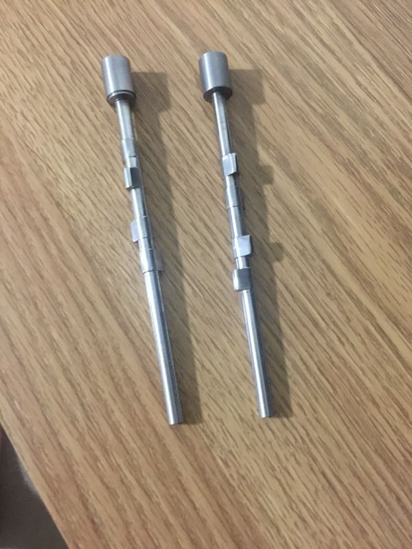
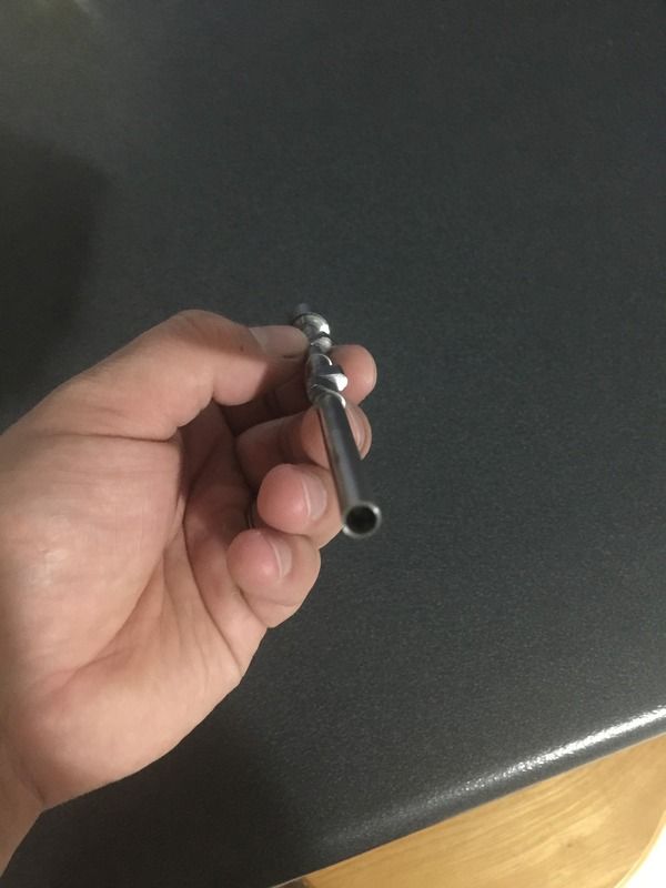
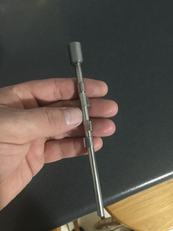
Cams are basically done. I just need to cut the end part off. Having the work piece fitted and being able to see what I was going to produce made the entire job so much easier. After I cut the first lobe I quickly realised that my initial angles were wrong and were quickly amended. All sorted now.
 
Parksy,
On the contrary, when a cam is manufactured all the timing events, lift, duration, lobe separation angles, acceleration ramp radius etc. are all taken into account otherwise they wouldn't know what they were making.
On my chart the lobe separation angle is created by my timing events, which are very mild numbers. The more radical the numbers the greater the lobe separation angle becomes.
Your confusion seems to be the lobe separation angle. This is not a fixed number, it changes as the timing events of the cam are changed, basically the overlap numbers.
I did a layout using your numbers. I hope this helps you to understand what is going on.
gbritnell

View attachment CAM LAYOUT 2.pdf
 
Thank you Gbritnell, I appreciate your time and efforts in explaining and coming up with that chart.

I'm 99% sure the cams I've machined reflect your chart.
Note: cam rotates CCW and the intake lobe is the inside one. Outer one(closest to camera) is exhaust.


When I install this to the engine. I'll have the degree wheel, find true top dead centre, set the crank to 30 BTDC and set the intake cam on cyl 1 to start opening. Will repeat this procedure for the other bank.
 
Parksy,
I may be having a senior moment, but don't your two cams need to be machined opposite to one another to account for their opposite running directions? It may be due to the way the cams are placed in the photo but it looks to me like they are identical? - Terry
 
Parksy,
I may be having a senior moment, but don't your two cams need to be machined opposite to one another to account for their opposite running directions? It may be due to the way the cams are placed in the photo but it looks to me like they are identical? - Terry

Like I said in the other thread, please correct me if I've made a mistake, but both cams are identical and will both run in the same direction.

Hope I'm not having the 'moment' here...
 

Latest posts

Back
Top