Vertical I.C. Rupnow Engine

Home Model Engine Machinist Forum

Help Support Home Model Engine Machinist Forum:

This site may earn a commission from merchant affiliate links, including eBay, Amazon, and others.
My Oilite bushings came in today, and they were all correct. I will put the Oilite part number on the appropriate drawings. I couldn't find a spring with the wire diameter I wanted for the intake valve, so I have one on it that has a 0.020" wire diameter on it. If it proves to be too stiff I will wind my own compression spring from .013" music wire. I have the pushrod with the little roller bearing on the end of it in place, and after what seemed a world of fettling and fussing, I have it running freely up and down when actuated by the cam. The spacer is finished and is setting between the crankshaft web and the main frame. I also fabricated a "cap" to restrain the connecting rod on the "throw', although I question how necessary it really is. In the pictures I have removed the ignition points, as they were only an old pair I keep for "fitting" when building engines. I will buy a new set of ignition points and a condenser tomorrow. All I have left to build is the rocker arm and it's support tower, and to make a head gasket. I still have to design a gas tank and support, but want to finish th entire mechanical aspect of the engine first, so I can release a download of all the pdf files.


Looking great Brian. If mine turns out half as nice i shall be happy.
 
Herby--I was wondering what had become of you. Did you remake the crank web? Holy cow!!! I just got an email with pictures from David in New Zealand, and he has about 70% of the engine built already. He is a new builder that I didn't even know about until right now. I will be ready to upload all the pdf files in about two days, but for now I will send him most of the pdf files I have saved. It feels really strange to set here in Canada and know that people on the far side of the world, as far from here as you could possibly get and still be on the same planet are building this engine.
 
  • Like
Reactions: gus
We're ready to rock and roll!! Rocker arm and support tower are installed, and as far as I know for the moment, those were the last two mechanical parts I had to make. I have to make a head gasket, put a stronger spring on the exhaust valve, and pull the crankshaft out and cut a keyway in it. For the initial run of this engine, I will steal a gas tank from one of my many other engines for a temporary set-up. Once I am convinced that the engine runs properly, I will design a tank and tank support for this engine and post the drawings. I have to go down street now and buy a new set of points and a condenser.
 
Okay guys--Pay attention. This is the complete electrical, or at least as much as you are going to get with this engine. Assuming of course that you use the points and condenser for an early Chrysler product which I gave the numbers for earlier in this thread. Bolt the points onto the flywheel side of the frame as shown. There is one electrical terminal with a nut on it. Put a ring terminal on the end of a piece of #14 ga. insulated wire about 18" long, and put both the ring terminal and the lead from the condenser on the threaded post and snug down the nut. I have also included a picture of the one ridiculously long tap I own, which happens to be a #8-32 and is just the right size for a bolt to hold down the condenser clamp.-NOTE--That hole is not on the frame drawing. Route the #14 ga. wire and the condenser wire around behind the condenser clamp ---we do NOT want them rubbing on the inside of the flywheel. A wire from the + side of the battery runs to a switch, then to the + side of a 12 volt automobile coil. another wire runs from the - side of the coil to a quick disconnect on the end of that #14 ga wire. Another separate wire runs from anywhere on the frame of the engine back to the - side of the 12 volt battery. When the points are closed, current flows from the battery, thru the switch and the coil and the points to the engine block and then back to the - side of the battery. Don't correct me--I'm not here to argue semantics. when the points open, it breaks the circuit, the primary field in the coil collapses and induces a high current flow in the secondery windings of the coil, and makes a spark which is delivered to the spark-plug. REMEMBER--the spark occurs when the points OPEN!!!


Last edited:
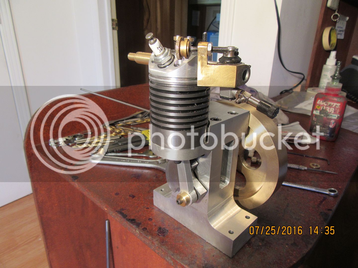
The engine is timed, both ignition timing and valve timing. BIG BIG HINT--Ignition timing is very easy to do with the cylinder head off and the flywheel off. Loosen the set screw on the ignition cam. Turn the engine over clockwise when looking at the flywheel side until the piston is at top dead center. (the flywheel is off, so you will be turning the crankshaft from the con-rod end.)Turn the ignition cam clockwise by itself until the flat side is against the ignition points rubbing block. At that time the points should be fully closed. Now just turn the ignition cam clockwise by itself until the points open.(This will happen very suddenly--it's not a gradual thing.) At the point where they open, tighten the set-screw on the ignition cam. Now turn the flywheel back and forth a bit and watch the points. What you want is for the points to spring open at the very time the piston reaches top dead center. There is a bit of leeway there, but aim for it happening right at top dead center. After the engine is running we can dabble about with advanced or retarded ignition. Since the ignition cam is on the crankshaft we will get a spark every time the piston is at top dead center. The spark that occurs on the exhaust stroke can be ignored---there isn't anything to burn anyways.
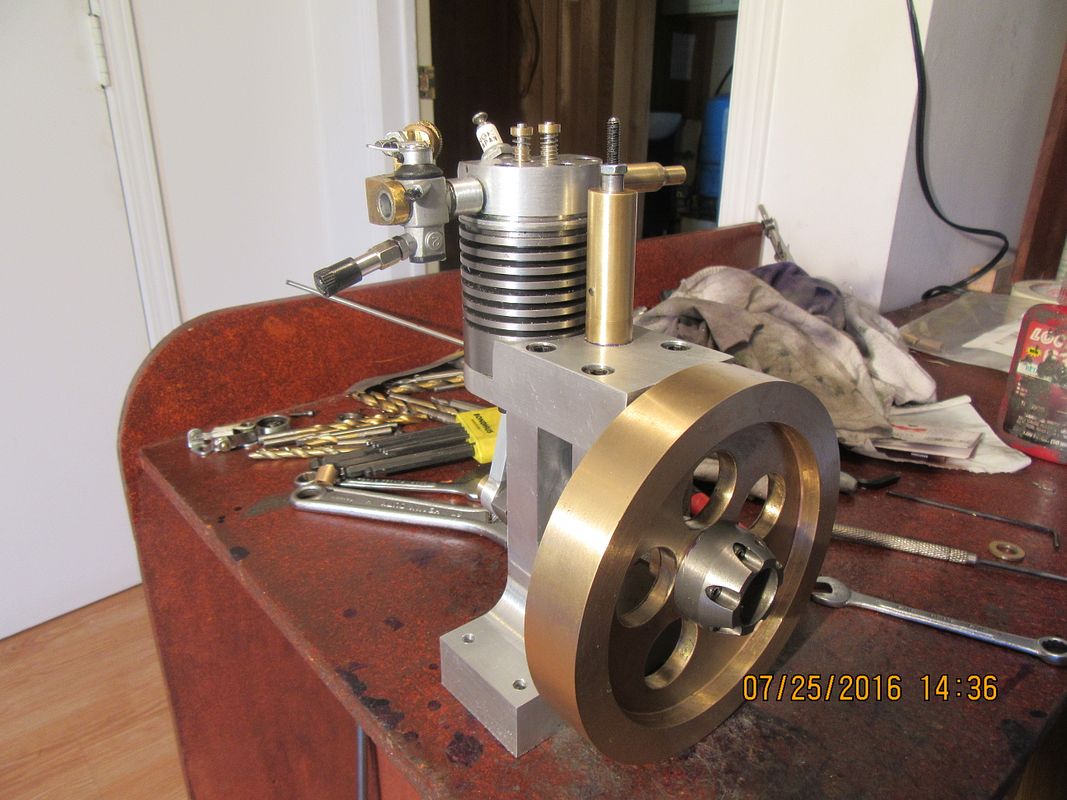
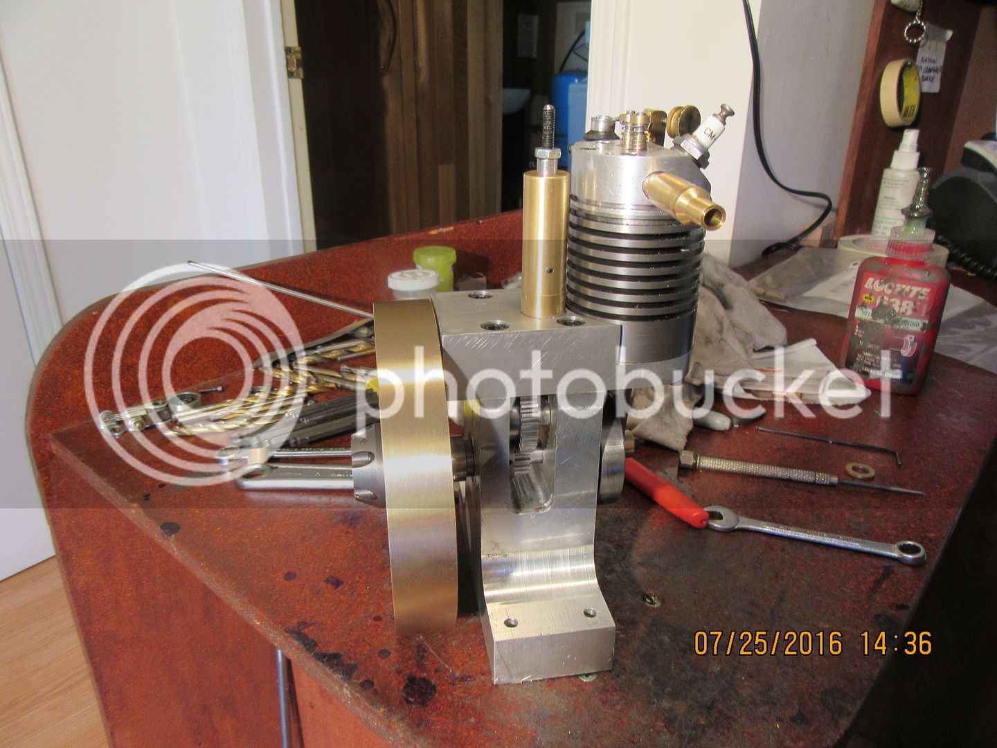
Put the flywheel back on, but leave the cylinder head off. Turn the flywheel clockwise (when looking at the flywheel side of the engine) until the piston leaves top dead center and begins to go down in the cylinder. Use a Vernier caliper to determine when it is exactly 1.3" from the top of the cylinder to the top of the piston. At that measurement, the crankshaft will be exactly 50 degrees before bottom dead center. Loosen the set screws on the crankshaft gear, and without letting the crankshaft turn, turn the crankshaft gear clockwise (same as the flywheel direction) until the cam gear (which will revolve in the opposite direction) just begins to cause an upwards movement in the pushrod. This is hard to see, and is best done while holding a finger so it is touching the end of the pushrod and the top of the guide at the same time.--You will feel it when the pushrod begins to move upwards, under the influence of the cam.) Lock the crankshaft gear set screws at this point. Use a magic marker to put a line on the flywheel in line with one of the corners on the frame, for a visual reference. Now, turn the flywheel clockwise while holding the pushrod down with your finger. On one revolution of the flywheel(which corresponds with the intake and compression stroke) the pushrod won't move. On the next revolution, (Which corresponds with the power and exhaust stroke) the pushrod should begin to move upwards when the "witness mark" on the flywheel lines up with the corner of the frame. This may take some major screwing about. Again, there is a bit of leeway here, but keep it as close as you can. And--if you see that the pushrod hasn't fully retracted at the beginning of the intake stroke, don't worry---the exhaust valve stays open about 20 degrees into the intake stroke.
 
Last edited:
  • Like
Reactions: gus
One more bit of information, and then I'm off to mow the lawn before my wife skins me-----The exhaust valve spring (as of this moment) is .022" diameter wire, 0.100" between coils when in a free state x 0.9" long in it's free state and 0.195" diameter inside.
 
  • Like
Reactions: gus
Hi Brian. Im still plodding along. Im on home oxgen due to emphysema which limits the amount of time i spend in the workshop. Dont like the idea of sparks and oxygen. Not sure if anyone else is on oxygen but would love to hear how they cope in the shop.
Anyway the new crank web is half done and i just sliced off a lump of steel for the flywheel. Pics to follow.
 
The engine is set up on my test bench. Fire extinguisher is close at hand. Video camera is up on it's tripod, and a borrowed gas tank is full and hooked up. Battery and all electrical connections are in place. Now I just have to wait for my wife to get up out of bed so I can make noise. wish me luck!!
 
Some other motors take longer to make and still they have complete set of drawing at the beginning. I think I lost something when translating but still thumbs up :thumbup:
 
Okay guys---here we are--First run. a couple of times you will hear a bit of clanking--the set screws came lose on the flywheel during the very first run. I made this video at about 9;30 this morning, but it took so long loading to YouTube that I had to leave it loading and go away for the day. I just returned home and see it is finished loading, so here is the first run---ever. I had one good long sustained run before I had to leave this morning--enough to satisfy me that the engine is going to be a good runner as designed.---Brian
[ame]https://www.youtube.com/watch?v=fp1Ja2-xt8g&feature=youtu.be[/ame]
 
And here we have the engine with a lighter intake valve spring and a slightly richer mixture than the factory carb setting. Engine seems very happy to run as long as I want to let it now. I had a lighter spring here, but it was just a tiny bit too small on the inside diameter to fit down over the spigot on top of the valve cage. I used an old jewellers trick for "sizing" wedding bands and forced the spring down over a tapered mandrel until it "grew" just enough to slide freely over the top projection of the valve cage. That was really all it took to get good long sustained runs.
[ame]https://www.youtube.com/watch?v=C0kky3Zaths&feature=youtu.be[/ame]
 
I originally planned on doing something really artfull and "swoopy" for the gas tank support, but practicality has taken hold. I decided on something simple, which would not only support the gas tank but would give some degree of height adjustability to the tank as well.
 
Don't get too excited about this stuff--it is all in the pdf download. I just wanted you to see that the gas tank and support have been detailed and taken care of.---Brian


Okay guys--here it is. Complete mechanical details of everything I have built on this engine as .pdf files, including assembly drawings and bills of materials. If you download it and build it, please let me know. If you have any questions, don't hesitate to ask me. There is a lot of work in the preparation of these drawings, and I don't ask any money for them. However I really do want to know if you are building and what your progress is. The skill range required to build this engine, based on a scale of 1 to 10, with one being a complete novice and 10 being an advanced machinist with two or three engines successfully completed is about a 7. Have fun!!!---Brian
https://www.mediafire.com/?fh7wnz2d4cgt0s4

Thanks Brian
for all the pdf files,
DavidLloyd2
 
I'm still making some progress. So far I have the flywheel, crank web and big end, con-rod, con-rod retainer, rocker arm and exhaust pipe completed. Plus half the carby. Still got a long way to go and my available shop time is about to dry up. Hoping to average a completed part per week until it's all done.

I found a tiny error on the carby body plans - the throttle stop screw hole is dimensioned as .294 deep, but then threaded 4-40 .394 deep. I have to ask - what does JAG stand for?
 
Congrats. It did run on the first start. Great engine. I am about to run the Howell V-2 next week. Will take a good break doing everything but engines. Trying very hard not to this new engine but my hands are itching. Will D/L your engine prints.
 
Back
Top