Shop building screw up

Home Model Engine Machinist Forum

Help Support Home Model Engine Machinist Forum:

This site may earn a commission from merchant affiliate links, including eBay, Amazon, and others.

Wizard69

Well-Known Member
Joined
Mar 9, 2013
Messages
1,388
Reaction score
285
View attachment ImageUploadedByModel Engines1448791046.088888.jpg

This little screw up began about three weeks ago. Needing some storage space under my work I took a piece of office desk top scored at an auction and cut it up to fit around the vertical columns. After gluing on the banding so nicely I suddenly realized that this shelf wouldn't fit between those columns no matter what I did with. After stewing for two weeks I finally said screw it and cut the shelf in half, glued it back together between the legs and then added a beam underneath not trusting the glue joint.

Really felt disgusted making such an armature mistake and for two weeks looked at that shelf with a bit of anger. Really hated cutting that nice bit of desktop in half.
 
Once designed a large filter unit about 3mx6m x9m h. After all fully assembled
i was told they couldnt get it thru the workshop doors.Slight redesign to sub assys
 
Hi

Years ago the City of Seattle built a new downtown jail. But when they went to drive the prisoner bus through the buildings big door it would not fit. So it took a year to get a new bigger door designed and built. By then the city had bought a new bus. Turns out it would not fit through the new bigger door.

Your tax dollars at work.

Mark
 
Way back when Kodak put up a nice new building with employee cafeterias, club areas, etc, as well as a swimming pool, they discovered one small problem. The pool was way up on the 6th floor, and they realized it would not take the weight of the water in the pool.... Whoops! :hDe: :rant: :fan:

Management claimed it never was filled since there were already a lot of other pools around town.... Yeah, right! It did get some use, they used it as a darkroom area to develop the huge billboard-sized photos they displayed in the train station in NYC.
 
Once designed a large filter unit about 3mx6m x9m h. After all fully assembled
i was told they couldnt get it thru the workshop doors.Slight redesign to sub assys

On a student placement, I sketched a load of duct work at a site, from which was issuing a noise problem. The company I worked for got the job to build the silencers, and they built them from my sketch...on which I had given radii but marked them as diameters.

I wish I had been there when the tiny silencer was taken from the van and offered up to the wacking great duct :)
 
Way back when Kodak put up a nice new building with employee cafeterias, club areas, etc, as well as a swimming pool, they discovered one small problem. The pool was way up on the 6th floor, and they realized it would not take the weight of the water in the pool.... Whoops! :hDe: :rant: :fan:

Management claimed it never was filled since there were already a lot of other pools around town.... Yeah, right! It did get some use, they used it as a darkroom area to develop the huge billboard-sized photos they displayed in the train station in NYC.


I've been working with more than a few Ex Kodak employees and have heard my share of very interesting stories.
 
Once designed a large filter unit about 3mx6m x9m h. After all fully assembled

i was told they couldnt get it thru the workshop doors.Slight redesign to sub assys


It does make you wonder how you missed the obvious. I was so pissed at this screw up that it took me two weeks to do the obvious fix, that is cut the shelf in half.
 
Mistakes - I've made a few, but then again too few to mention....

Ah Frank had it too easy....

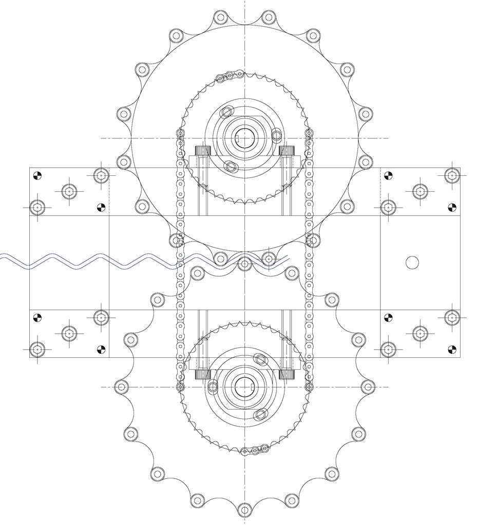
This is an extract from a machine I designed / built for making the wrinkled wire you see in those shelving systems in supermarkets.


MISTAKE.jpg


See if you can spot the blindingly obvious mistake ?

Regards,
Ken
 
Both wheels trying to rotate in the same direction. Rof}Rof}
 
Oh, the shelf won't fit syndrome ! Where have I seen that before ? :rolleyes:

Brian
 
Well spotted - the wheels must turn in opposite directions but the chain drive makes them go the same - and they collide.

Only became apparent on assembly.

Definitely a Duuuhhhh moment for me.

All was not lost - it was proof on concept in any case and most of the bits went into the final build.

I still can't believe I did that to this day.

Regards,

Ken
 
Ken.

At least you salvaged most of it. In any event at work we must have hundreds of those wire carts and I've often wondered how the wire was bent. Now I know.

This brings up a question though, how much power do you need to drive that mechanism? I wonder about the viability of a hand crank machine to do similar one offs. With smaller wire it would also have application in model engineering.
 
That version was believe it or not - hand cranked - with a 500mm long handle and it was really tiring to operate on 3/16" wire for more than a few seconds.

Note also the angular adjustment slots - whilst drawn symetrically this will produce an asymetric wrinkle and you have to adjust the angular offset to fix it.

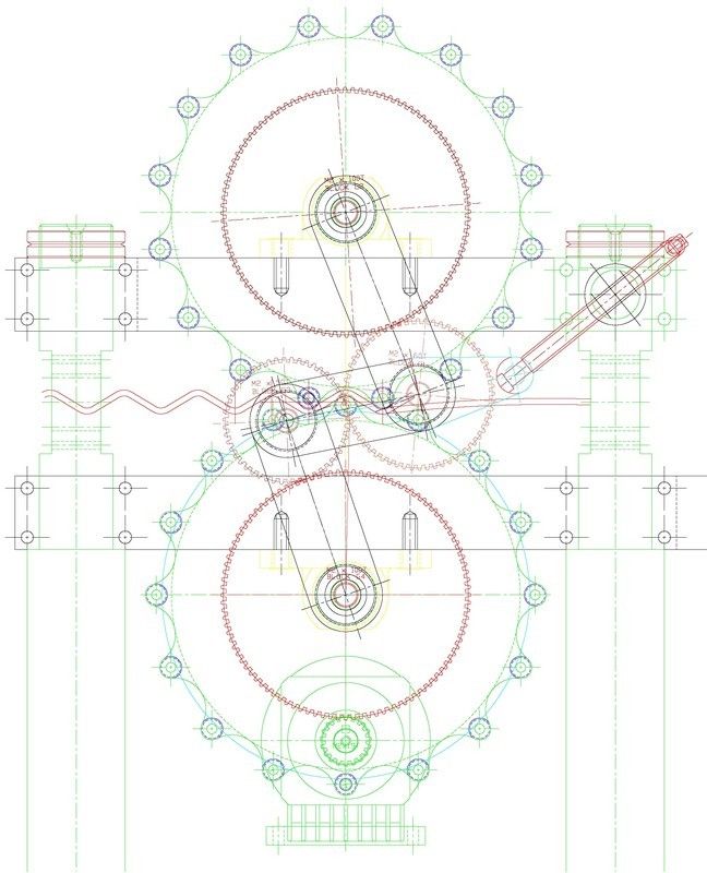
The final machine uses 1 H.P. and an offset gear-train so that you can adjust the angular offset on the fly - see photo below.

The motor is geared down to a final speed of the wrinkling wheels of 14 rpm.

The offset varies with wire thickness and type (stainless or mild steel).
Mistake2.jpg

Regards,
Ken
 
There is a difference between gears and sprockets...
 
That version was believe it or not - hand cranked - with a 500mm long handle and it was really tiring to operate on 3/16" wire for more than a few seconds.
My first thought was model engineering so 3/16" would be pretty heavy.
Note also the angular adjustment slots - whilst drawn symetrically this will produce an asymetric wrinkle and you have to adjust the angular offset to fix it.
Do you mean phase between the upper and lower wrinkle wheels? Or is this some sort of different angular offset?
The final machine uses 1 H.P. and an offset gear-train so that you can adjust the angular offset on the fly - see photo below.
I'm missing something in my understanding here. In any event how easy is it to change the wrinkle wheels? A machine like this gives me all sorts of ideas.
The motor is geared down to a final speed of the wrinkling wheels of 14 rpm.

The offset varies with wire thickness and type (stainless or mild steel).

Regards,
Ken
 
Changing the wheels was never envisaged - it would also change the distance between them if you change the "depth" of the wrinkle or the pitch of the wrinkle as that would also change the wheel diameter.

Starting from scratch with that in mind you might be able to design in adjustment points.

As regards the offset - if the upper and lower roller are symetrically lined up (as per the photos) then the wrinkle comes out "sawtooth" unequally angled sides.

So you have to be able to angularly adjust one wheel relative to the other to correct it. The prototype design had slots which are a hit and miss affair to set and you obviously can't change it while the machine is running.

The second version had an unequal pair of idler gears which if moved from side to side changes the relationship between the two wrinkling wheels.

Hope this helps.

Regards,
Ken
 

Latest posts

Back
Top