Cx701 lathe report

Home Model Engine Machinist Forum

Help Support Home Model Engine Machinist Forum:

This site may earn a commission from merchant affiliate links, including eBay, Amazon, and others.
Hi Brian,
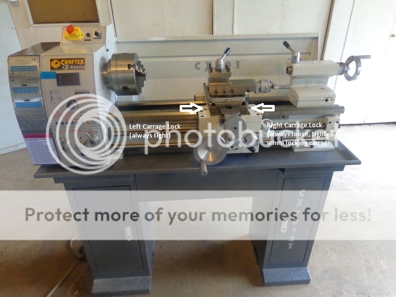
I had power feed on my old Emco V10P lathe (which I think was about the same size as your Cx701) and I really liked it.
If I wanted to machine up to a shoulder I would set the stop on the lathe bed, engage the power feed and disengage it a mm or so before the carriage hit the stop. I would then use the wheel on the side of the lathe to move the carriage up to the stop.
The only problem is that you need to pay close attention so you don't run the carriage into the stop under power, so you should run a slow power feed rate until you gain confidence in your ability to disengage it in a timely manner.
Hope this helps as power feeding is a great advantage.
Regards,
Alan C.
 
My bad, guys!!! I had mistakenly made the quick change toolpost nut about 0.140" too thick. It worked fine, but interfered with the travel of the topslide. I gained almost exactly 1" by trimming the thickness of the nut. It still isn't the full 3" as the literature specifies, but it's much better than it was. My total top-slide travel now measures 2.630". Sorry about that!!! I have not updated the drawing I posted earlier in this thread to show the correct dimension because this idiot website will not let me go back and edit a post, so be warned, the drawing posted earlier in this thread is incorrect. The drawing posted here is correct.
 
Hi Brian:

Doesn't your big saddle hand wheel have graduations? If so can't you use those for longitudinal movement?
You'll find a DRO indispensable even if just to eliminate the pain of backlash. I abandoned using the graduated hand wheels shortly after I got my lathe. Especially since the graduations on my carriage hand wheel were goofy. I suspect I have a metric machine with inch graduations. It makes no difference now that I have the DRO's
You won't regret adding a DRO to both axis.

If I turn my top slide parallel like you have it the tail stock runs into the handle. This happens when for instance you have a short piece in the chuck and you bring up something like a center drill in the tail stock.

I rarely use the top slide except to turn short tapers so I always keep it at an angle of about 29deg so it's ready to do threading and I just leave it there. As you said it's sort of useless to limit your long travel to the length of the top slide and way too much trouble to reset it.

If I want to do a small chamfer I just turn the tool post around to present the side of the tool bit to the corner at whatever angle by eye (usually around 45 or so). The tool post is easy to turn and it doesn't matter too much what angle you set it to for normal machining. (I use carbide inserts).

BTW You (and others) have more balls than I to try parting off under power. Keep your safety glasses handy. I've had parting tools dig in even under hand feeding resulting in flying parting tool pieces and damaged parts.
A nice project is to make yourself a rear tool post for your parting tool. It works so much better and there's little chance of it digging in and causing problems. You can usually leave it in place all the time if you have enough cross feed.

My 2c

<edit> I may have used the term "top slide" where I meant "compound". I forget the proper terms. Anyway hopefully you get what I mean.

Sage
 
Last edited:
Brian

Thanks for this thread. I have the same lathe and, as it is my first lathe, have been learning as I go. I too had issues with Busy Bee trying to recommend a tool post. I found that, by their own admission, the Barrie store was much more experienced with woodworking than metal working. The Whitby and Concord stores were much better.

They recommended a different toolpost, but it will need modification, so I have not installed it yet as I am inexperienced and afraid to make scrap metal out of either my lathe or the toolpost :)
 
Sledjunk--Really, the quickchange toolpost they sell fits on this lathe with no modification to the lathe or to the toolpost if you make the nut I posted. The only limiting factor is that the largest cutting tool you can use is a 3/8" square one. Where are you located?---Brian
 
Sledjunk--Really, the quickchange toolpost they sell fits on this lathe with no modification to the lathe or to the toolpost if you make the nut I posted. The only limiting factor is that the largest cutting tool you can use is a 3/8" square one. Where are you located?---Brian

Brian
First off. OOPS! My lathe is a CX 706 not 701. It is a smaller version.
Doh2.gif


I am in Pefferlaw, so basically across the lake from you.

This is the QCTP that Busy Bee recommended, http://www.busybeetools.com/products/TOOL-POST-QUICK-CHANGE-FOR-MINI-LATHE.html but it would need some modifications, either to the QCTP (open the bore at the bottom to allow for the larger flange on the bottom of the tool post mounting stud) or alternatively, modify the combination slide to replace the tool post mounting stud.
 
I have a problem, and it may not be as large as I see it, but it is a problem nonetheless. This lathe has has no carriage "lock" on it. There is a way to lock the topslide in place and there is a way to lock the cross-slide in place, but there is no way to lock the carriage in place on the ways. This is probably a good marketing strategy for Craftex, because if there was a carriage lock on it, sure as Hell somebody would lock the carriage, forget they had done so, and then engage the power feed and break something. You can "kind of" lock the carriage in place by not engaging the power feed at the gearbox and putting the lever on the front of the apron in "power-feed" position. This stops the carriage from being moved with the big hand-wheel on the front of the apron, but it will move (As measured with dial indicator) 0.019" left to right because of backlash in the power feed mechanism in the apron. This isn't a lot, but it becomes HUGE if you are doing anything like machining the rod journal on a crankshaft, as shown in the pictures. The slot is only .375" wide. The journal when turned to finished diameter will be .375" diameter. This means that to machine it, you must use a tool with a lot of "stick-out" from the tool-holder, because of the offsets in a typical crankshaft. I have machined the "sides" of the journal to finished dimension. Now I have to move the tool in and finish turning the journal to finished size. (It is 0.430" diameter right now.) The tool is .125" wide. So--the tool only has to traverse 0.25" in total left to right to take this finish cut on the diameter. With a good set of carriage stops mounted to the front "way" on the lathe, I could turn the wheel on the apron and move the carriage left to right, depending on the carriage stops to prevent going to far and have the turning crankshaft whack the top of the tool and break something. I find the movement you get by turning the wheel on the front of the apron to be very "coarse" and to not give a very good "feel" for what the tool is actually doing. I prefer to make the tool move left to right or vice-versa by turning the feed handle on the topslide. This gives me a much better control of the tool movement.---I can design and build an adjustable "travel limiter" which I can set up to limit the amount of travel of the topslide very accurately.--But---I still have that damned 0.019" of slop in the carriage to contend with. So--Okay--I can design and build a "carriage lock" that will securely lock the table in place as well---but it must be a "lock" which can slide without damaging the carriage or the ways or the gearbox if the "power feed" does accidentally get engaged. I can do that too--but now it's beginning to become a lot of extra work. This is definitely not a job where the power feed would ever be engaged but, "stuff happens". How do other folks with this lathe, or a clone of it handle this situation?---Brian

 
That really sucks not having a carriage lock! I thought all lathes had one.
Can't help directly though as I have no experience with that lathe.

Pete
 
Hello Brian,
I have a 9 x 20 lathe similar generics to yours, and used a simple carriage lock mod fro Steve Bedair's web site. Simple, effective and easy to do. Works great for me.
Regards, Norm
 
Hi Brian,
I have the smaller version of your lathe (WM 250) it has a saddle lock but as delivered it doesn't work. On mine there is a small 'L' shaped block on the right hand side of the saddle that hooks under the bed just in front of the rack. This stops the saddle lifting but it also has a slot sawed half way through it so that one end will bend up and clamp to the bed it is worked by one of the allen headed bolts on top of the carriage. There is no way this block can bend, it is much too thick, so to make it work they leave the other screws loose!! I modded mine by cutting the block in half and fitting a lever to it to make it work (see saddle clamp on my website ). The photo shows removing the block, the line of three holes parallel to the bed are where it is held in place. The largest hole is for the clamp allen bolt and the two smaller ones (which were left loose) hold the guide block under the saddle. Is there anything similar on your lathe, if it is like mine it won't work without some work!

Cheers
John

carriagelock.jpg
 
Last edited:
Hi Brian:

Ditto what Journeyman posted. I didn't think my lathe had a carriage lock either but I found a tall loose nut sticking up on the top of the apron apron one day and found out it was a lock that you had to turn with a wrench. The nut pulls up on a bolt that apparently pulls up on some sort of clamp on the ways. It has to be oriented just so or it doesn't clamp. I thought about putting a handle on it but sometimes it has to be turned /released more than a turn to activate / deactivate. Perhaps you have missed something. Try a wrench on everything in site. But then - I'm sure you already have.

Sage
 
Like dsage said it's not very obvious but the carrage lock is on the right side. On carrage assembly you have three allen bolts on each side the top one on each side are what locks it. On mine the left one is tight and the right side is loose. When tightened it will lock the carrage. Its hidden from view but I took one of your pictures and indicated them. Hope this helps.
carrage%20lock.jpg

Lathe.jpg
 
I replied to Brian on another forum but to save those on here posting their warco etc carrage stops the latest batch of big bore 280mm swing machines don't have a carrage lock. Though these also have tapered gibs on the cross slid ewhich brian's does not.

Possibly due to a lareg number of them having DROs fitted which cover the screw.
 
Dhoulton--Thank you, Thank you, Thank You!!!! That is indeed a carriage lock. I would have never known that in a hundred years. I just tried it on mine. This is bloody marvelous!!! Now I can go ahead and build an adjustable travel limiter for my topslide. I will post plans/pictures when I do that.---Brian
 
Your welcome Brian. I have the same lathe only the U.S. version (Precision Matthews PM-1127-VF-LB). Same but different color scheme. I've had mine for a few months now and have had to figure out a few things also. If I can help in any way let me know. My latest upgrade was to figure out how to put a DRO on it. That was a real dilemma for the cross slide.
 
I am experiencing what seems to be an out of balance 3 jaw chuck. (the one that came with the lathe.) It reads .002" total indicated runout on a 1.25" diameter ground and polished shaft held in the jaws and measured 1" out from the chuck jaws, which is perfectly acceptable, but I am getting a bad "out of balance" vibration between 600 and 700 rpm. No bouncing and vibrating below 600 rpm, and absolutely no vibrating and bouncing when ran with the chuck removed, spindle only. This seems to indicate to me that the chuck itself is out of balance. Has anybody else with this lathe and chuck noticed that "out of balance" issue?
 
Hi Brian:
You've had that lathe for some time now. Was it always that way. Dumb question since I guess you would have noticed. Maybe it has collected some swarf inside somewhere. Hows the TIR on the outside of the chuck body? Seems unlikely but maybe the body was made out of round. OR how about the mounting plate outer circumference not round.
Strange. Keep us posted.

Sage
 
dsage--That is the chuck that came on the lathe. It didn't have a vibration when I bought the lathe a year ago, and I haven't had any catastrophic events since I bought the lathe.. --nothing has changed. I can't remember for certain, but knowing me I would have wound that chuck up thru all the rpm ranges when I first bought the lathe and chuck together, brand new, checking for any unbalanced condition. Today will be spent running with jaws fully closed, with jaws removed, etcetera.---Brian
 
I just tried the chuck from 0 to 700 rpm with the jaws tightly closed, no material held in the jaws. Vibration is still there at around 620 rpm, just not quite as pronounced.
 

Latest posts

Back
Top