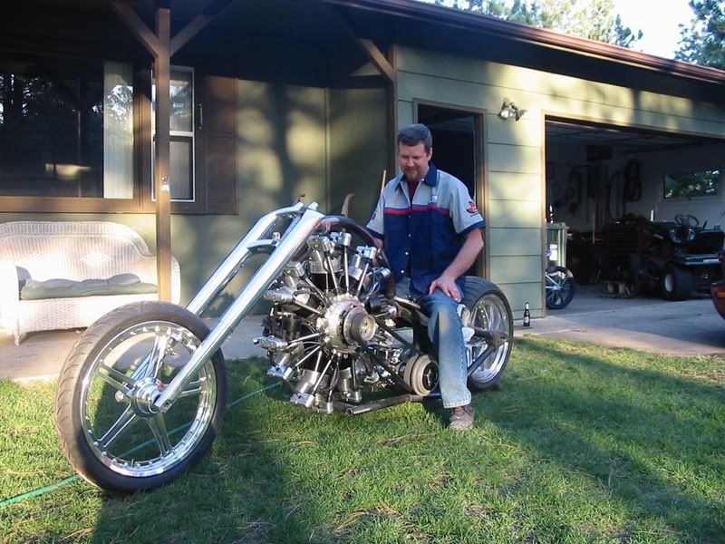
Another Radial - this time 18 Cylinders

Home Model Engine Machinist Forum

Help Support Home Model Engine Machinist Forum:

This site may earn a commission from merchant affiliate links, including eBay, Amazon, and others.
Mattsta,
They are all imperial gears 14-1/2 deg pressure angle and assorted DP depending upon the particular gear. Did you have a question about a particular gear? - Terry

Hi Terry.

Well.......all of them really!

I guessed they were 14 1/2 gears from the shape of the teeth

I was looking at the teeth you cut into your crankshaft and was wondering what size the gear is. I assumed 16 teeth on a 0.5" PCD since this a standard regularly available gear size (32 DP) and with the addendum added, the OD of the gear would be just slightly smaller than your main bearing journal. This is all assumption on my part however!

I've designed a set of gear templates in Pro/Engineer CAD software and I can create any spur or helical gear in any configuration I like in a matter of seconds. I have input paramaters for PCD, number of teeth, pressure angle and helix angle (which is set to zero for straight cut teeth).
 
Mattsta,
The front and rear cam drive gears that I cut into the crankshaft were .5PD, 16t, and 32 pitch. I made the (tiny) cutter to cut these integral gears. And, your assumption about their diameter is correct.
The large jackshaft gears were 1.0PD, 32t, and 32 pitch. I used a commercial gear cutter to make these.
The small jackshaft gears were .5PD, 12t, and 24 pitch. I also used a commercial gear cutter to make these.
The oil pump drive gear was .938 PD, 30t, and 32 pitch. Again I used a commercial gear cutter to make this one.
The internal cam rings were 2PD, 48t, and 24 pitch. I purchased these from Amazon, of all places.
The distributor drive gear and the driven gears were commercial gears H-2410R and H-2420R, respectively, also purchased from Amazon. - Terry

Awesome!

That's saved me some serious head scratching!

Thanks Terry
 
We've been out of town for several days attending my grandson's birthday, but while the nice weather continued I managed to add runtime to the radial. So far, I've accumulated about 45 minutes of two minute (full tank) runs at various rpms with complete cool-downs in between. I've checked the plugs several times, and the results are pretty much always the same. The front and rear row plugs are always similar and have acceptable colors. The bottom plugs in both rows still show slightly leaner running conditions compared with the plugs in the upper cylinders. The final plug photos show these results which are still a bit of a puzzle when compared with a typical nine cylinder Hodgson-type radial.
I've done some thinking about this unexpected difference using a SolidWorks assembly model of the rear section of the engine. The lean conditions in the lower cylinders are probably created by the distributors which protrude into the plenum just ahead of the carburetor. The T-18's dual distributors with their relatively large helical gears take up a considerable portion of the plenum volume between the carburetor and the impeller. Much of this 'blocked' volume is below the center axis of the impeller; and, as such, the fuel distribution may be biased toward the upper portion of the plenum. One of the photos shows the rear section of the engine including the distributors behind a transparent model of the impeller. It's an interesting but very minor result given the engine is a running display model.
One-eighth turns in either direction of the idle disk still have little effect on the idle which is more of a mystery. But, the engine is capable of reliably idling at 900 rpm when the disk is within an eighth turn of its stock position, and I'm totally satisfied with that. If I were using a larger prop, I'm pretty sure I could throttle the engine down a few more hundred rpm.
I'm still not yet recirculating the oil since the bluing on the cylinder walls is still being polished off by the rings. There has only been about a pint of oil flushed through the running engine so far. Closing the oil loop is the last step that remains before the engine is retired to a shelf in my shop, and then I'll start thinking about the next project. I don't plan to make another video, after all, since my last attempt ended up with even poorer quality than the original video I made. - Terry

900.jpg


901.jpg


902.jpg


903.jpg


904.jpg
 
Watching and soaking up all your experience building this fanstastic engine.
V-2 material not in yet. Gus idling and surfing net.
Take Care.
 
Hi Terry
Come on, those plugs look great ! I do not see enough difference to be of any concern.
I have a 1969 AMX with a 390 and a cross ram dual quad manifold with a large plenum and 2 650 double pumper Holley's. My 8 plugs show more variance than yours. And my car runs like a rapped ape.
I think that you may be being just a tad too critical. What you have done is an absolutely amazing accomplishment. And you did it in a miniature scale, plus it sure sounds good.
I really hope you reconsider the "no new video" statement.
Another vid from the firewall side would be really great, tach, throttle and all the good stuff you have spent so much time on. please, please, please.......
I'll send you my camera if you want.

And once again, thank you very much for taking the extra time and effort to share it with all of us.

Scott
 
Closing the oil loop is the last step that remains before the engine is retired to a shelf in my shop, and then I'll start thinking about the next project. I don't plan to make another video, after all, since my last attempt ended up with even poorer quality than the original video I made. - Terry

R-4360 Terry!

You know it makes sense!

;D
 
Hi Terry!

First of all I want to congratulate you to your fantastic work!

I`m sorry that I didn`t answer your question on the youtube comments. I have overlooked it. If I had known of your project a little bit before maybe I could have answer you a lot of questions.

It looks like you have cut out two windows into the cover plate of the impeller to get space for the distributor drive. My engine has a solid cover plate without any holes. Maybe this is the reason for the leaner lower cylinders but i would not change anything on your engine. In my opinion your spark plugs look really good.

I havn`t found better pictures but you can see how it looks like.

And an additional picture where you can see the oil sump ;)

Regards,
Christian

100_0705.jpg


DSC_0017.jpg


100_1100.jpg
 
Christian,
Thanks very much for your comments. For the rest who have been following my build, if you look back at my very first post you'll see that the Chaos_Industries' build was the original inspiration for my engine. I downloaded and carefully studied hundreds of their online build photos to come up with the design of my engine. My Hodgson 9 drawings were an additional resource for the cam rings and front crankcase section. I built only one engine, but they built two at the same time!
A difference between our engines is, as Christian points out, that my air guide is integral to the rear cover; and I machined clearance cavities for the lower ends of the distributors instead of completely 'shelling' out the rear cover. My rationale for going this way was to reduce the volume of what seemed like an overly large plenum, but my decision was based more upon groundless instinct than any science. In the end, my distributors are likely influencing the flow - for better or for worse - more than the distributors in Christian's engines.
Another difference, and this addresses Charles' question, is the number of blades on my impeller. If you compare the photo of my impeller with Christian's photo, you'll notice his has nine blades which matches the number of input ports while mine has only seven. I used seven blades because that was the maximum number I could fit into the available machining space using the profile cutter I had. I could have changed the machining strategy and used a smaller cutter, but I was afraid the resulting chatter would have been unacceptable in my particular setup. So, instead, I tried to come up with a design reason to justify seven blades. The only thing I could come up with was that when it came time to install a nine blade impeller, I might end up with an unfortunate positioning that would consistently block an intake port during a critical portion of the intake cycle. At the end of the day this didn't pass the B.S. test, but along the way I realized the exact number of blades probably wasn't really critical.
So, Christian, I can't help but be curious about your own results. I've watched both of your YouTube videos and your engine(s) run really well. Do they also start easily, and do you see any differences in your plugs between the upper and lower cylinders or between your front and rear cylinders?
By the way, another great feature of your engine that I really wish I had incorporated into my own are the pushrod tubes. Without them, there is just no way to eliminate the prop wash-induced oil spray created by the seepage around the lifter bushings, especially on cold start-ups. - Terry

905.jpg
 
Engine in very magnificence
Good job my friend.
:bow::bow::bow::bow::bow::bow::bow:
 
I thought it might be interesting, if not prudent, to do a few calculations on the engine's power handling limitations. These calculation might be useful to others when it comes time to select a prop for their own radial. The first calculation is the maximum torque, from a materials perspective, that the crankshaft is capable of handling. In this engine the full power is transmitted to the propeller through the front crankshaft section. The average diameter of this section is .500", but there is a short portion just forward of the cam drive gear that is only .420" in diameter, and this is likely the weak point of the shaft. These first order calculations ignore any effects from stress risers in the corners left behind by machining as well as the 1/8" diameter PCV vent that was drilled through the front section.
The T-18 crankshaft is constructed from 12L14 steel which has a yield strength (tensile) of about 60,000 psi. Since the crankshaft is torsionally loaded it's the torsional yield strength that's of interest. This is typically estimated at 60% of the tensile value which, for 12L14, is about 36,000 psi.
From high school physics, a torque T (in-lbs) applied to a shaft of diameter d (inches) creates a torsional stress s (psi) according to the expression:
s = 16 * T / (pi * d^3)
The torque corresponding to the torsional yield stress at the crankshaft's weak point is:
T = s * pi * d^3 / 16
T = 36,000 * pi * .420^3 / 16
T = 523 in-lbs
T = 44 ft-lbs
This number is in line with the destructive test results I recorded earlier during the design of the crankshaft.
The T-18, being a display model, is run only under static conditions. That is, a prop is fitted to the crankshaft, and the engine is run while being fixed to a bench. As a result, a static thrust is generated by the prop which tries to pull the engine forward, and the crankshaft is loaded by the power creating this thrust. The amount of thrust is dependent upon the pitch and diameter of the prop, the engine rpm, and the air density. An online static thrust calculator such as the one located at: http://personal.osi.hu/fuzesisz/strc_eng/ can be used to compute this thrust as well as the power generated by the engine. For example, with the current three blade, 28 x 12 prop running at 3500 rpm, this calculator predicts the engine will generate about 30 lbs of thrust and 3 hp. The horsepower can be easily converted into crankshaft torque using a well known equation relating the two:
Torque (ft-lbs) = HP * 5252 / RPM
While the engine is generating 3 hp at 3500 rpm the crankshaft torque is:
Torque = 3 * 5252 / 3500
Torque = 4.5 ft-lbs
which is an order of magnitude lower than the crankshaft's yield point. (NEMA standards use much larger safety factors for electric motors since they must contend with loads having high torque starting and stall conditions.)
The forward thrust which is totally supported by the engine's front bearing should also be considered. The T-18 crankshaft is designed so its loaded front section can move forward a few thousandths until a shoulder located just forward of the weak point contacts the inner race of the front bearing. This bearing is a generic 1/2" i.d. deep groove ball bearing. The axial load rating for these bearings is a complex quantity and is generally unspecified. An axial load pushes the balls up and onto the flat side of the race where the increased contact pressure and surface finish increase the probability of brinnelling. Conservative designers wishing to not impact bearing life with excessive axial loads will limit them to a few percent of the bearing's specified radial load. In this application, however, where dozens of hours of bearing life may be sufficient; an arbitrary 10% load factor may be acceptable. The radial load rating of the T-18 front bearing is 500 lbs which gives an arbitrary axial load rating of 50 lbs.
Shaft hp is a sensitive function of rpm in a statically loaded run. Using the same propeller, but running at 5000 rpm, the calculator predicts an increase in thrust to 60 lbs, and a shaft power of almost 9 hp. This level of output power is at the edge of any reasonable estimate of this engine's capability and is likely beyond the volumetric capacity of the existing carburetor. At this rpm and power level, though, the crankshaft torque increases to nearly 9.5 ft-lbs.
There is still almost a 5X safety factor at this increased level of torque, but it is common practice to maintain at least this level of margin to guard against second order effects such as fatigue and repetitive stress loading.
It is certainly possible to select a prop that will load the crankshaft dangerously close to its yield point even at a modest 3500 rpm. A three blade 36 x 16 prop is also available, and this prop will load the crankshaft with nearly 17 ft-lbs of torque in a static run. - Terry
 
Conservative designers wishing to not impact bearing life with excessive axial loads will limit them to a few percent of the bearing's specified radial load. In this application, however, where dozens of hours of bearing life may be sufficient; an arbitrary 10% load factor may be acceptable. The radial load rating of the T-18 front bearing is 500 lbs which gives an arbitrary axial load rating of 50 lbs.

Just for a bit of extra info, when I worked at SKF and we had to design bearing arrangments, the basic guide was deep groove ball bearings could accept axial load in the order of 10% of actual radial load, rather than rated radial load. As the actual radial load of the bearing increases, the chances of skidding, or sliding ball contact is reduced. So in very light radial load situations, the axial load capability can be very low indeed.

I think you'll be perfectly fine in this engine, but I thought I'd mention it in case it influenced you bearing choice in future projects.
 
....As the actual radial load of the bearing increases, the chances of skidding, or sliding ball contact is reduced. So in very light radial load situations, the axial load capability can be very low indeed.....

Cogsy,
Thanks for your experienced comment. It makes a lot of sense and is filed away for future reference. It probably explains why motorcycle wheel bearings can survive the side loads they encounter in lean turns. - Terry
 
Thanks to everyone for following my build and also for your comments along the way. I'm working on a second video as requested by Scott who's been religiously following this project from its start.
I plan to start another long term build, but it's been difficult finding another engine into which I'm willing to invest years of effort. I've developed a fondness for the WWII aero engines, but I'm not aware of any bar stock plans with the right level of complexity to keep me interested, and I'm not sure I want to build another radial right now.
The Rolls Royce V-12 Merlin, probably the most influential WWII-era engine used in the British Spitfire and American P-51 warplanes, has all the complexity I could ask for. I was fortunate to have purchased what might be the last available complete set of castings from the owners of Dynamotive, a small (now defunct?) San Diego start-up that planned to build and sell quarter scale Merlins a decade ago. I don't believe they ever produced any engines but instead sold off the castings they had so laboriously created to individuals to build their own.
The castings I received were investment cast and can be best described as large pieces of jewelry. They include all the intricacy and realism that was a part of the full-size engine.
I've no experience in working with castings, and was taken back by the note accompanying them that being long, complex, and thin-walled; they will likely require straightening and, in some cases, heat treating.
My set of castings includes those for a functional supercharger, but it's not clear whether its scaled development was ever fully completed or just how much of it became a part of the prototype that was produced. The original designers opted for a glow plug engine, and so the magneto development was never completed. Finally, the notes mentioned fuel distribution issues with the Merlin's scaled-down intake manifold. The developers eventually designed an alternate configuration with multiple carburetors in order to get their prototype to run, but there doesn't appear to be information on its design. Over-heating issues were also mentioned, and I noticed a prop was never fit to their running prototype. Working these issues will hopefully make the project interesting, but I wish it wasn't going to involve very expensive and irreplaceable castings.
I've been able to find online evidence of only three other builders who have tackled this project using these castings. One posted his crankshaft build on 'the other' forum but he never returned after producing his own piece of art.
My plan is to spend the next month or so evaluating the castings I have so I can better understand the issues involved with straightening them. My first goal will be to get the castings to a point where, through straightening and minimal machining, they fit perfectly together before I commit to the project and begin making parts for it. My plan B is the same plan B I had for my 18 cylinder radial project, and that is to build Ron Colona's 270 Offy. -Terry
- Terry

906.jpg
 
Last edited:
Thanks Terry !

The Merlin sounds like an awesome project. Back in the 70's I saw a car at the drag strip named "Allison Thunderland" A thunderbird with an Allison V12, it had quite a unique sound. I was looking on Google to try and find a picture and stumbled across this , Just in case you needed something to do with the "18"

radialenginebike1.jpg


:)

Scott
 
My first goal will be to get the castings to a point where, through straightening and minimal machining, they fit perfectly together before I commit to the project and begin making parts for it. My plan B is the same plan B I had for my 18 cylinder radial project, and that is to build Ron Colona's 270 Offy. -Terry
- Terry

Cant wait to hear your evaluation details Terry. The ultimate decision will be a win-win for us regardless of what you decide. But I think you should build us a dynamometer in the meantime... just to keep the hands busy :)

I was about to 'wonder out loud' if your SW + CNC proficiency could replicate castings from bar stock on a design of your own choice... kind of along the lines of what Mr. Britnell does on manual mill with post-blending & finishing.
http://www.modelenginemaker.com/index.php?topic=3846.165
Guessing this method brings forth different challenges & trade-offs; work holding, post machining distortion, no reverse cavities etc. Maybe more applicable to simpler/earlier gen V12 like a Liberty?
http://en.wikipedia.org/wiki/Liberty_L-12#Variants

But I get the sense you are targeting something even meatier :) The detail & intricacy of those Merlin castings... gosh, jewellery for sure. So they are no longer available in case of machining mis-steps?
http://www.quarterscalemerlin.com/prices.htm

Another link FYI showing some analogous casting & engine components. Don't know anything about it though.
http://pace-engines.com/index.php?ID=1
 
Cant wait to hear your evaluation details Terry. The ultimate decision will be a win-win for us regardless of what you decide. But I think you should build us a dynamometer in the meantime... just to keep the hands busy :)

I was about to 'wonder out loud' if your SW + CNC proficiency could replicate castings from bar stock on a design of your own choice... kind of along the lines of what Mr. Britnell does on manual mill with post-blending & finishing.
http://www.modelenginemaker.com/index.php?topic=3846.165
Guessing this method brings forth different challenges & trade-offs; work holding, post machining distortion, no reverse cavities etc. Maybe more applicable to simpler/earlier gen V12 like a Liberty?
http://en.wikipedia.org/wiki/Liberty_L-12#Variants

But I get the sense you are targeting something even meatier :) The detail & intricacy of those Merlin castings... gosh, jewellery for sure. So they are no longer available in case of machining mis-steps?i
http://www.quarterscalemerlin.com/prices.htm

Another link FYI showing some analogous casting & engine components. Don't know anything about it though.
http://pace-engines.com/index.php?ID=1

Peter,
I studied these castings also wondering if I could duplicate any of them if I happened to ruin one or two. Except for only a few simple cases the answer is pretty much no. The reach with long skinny profiling tools into the interiors of a typical part is beyond my and my machine's capabilities.
I don't know how George B. does what he does manually. When I was at the Ohio show last year I got to see inside a few of his masterpieces where he had left the finish as machined with no filing. The interiors looked like perfect roughing-pass CNC surfaces. I couldn't see any 'oops' areas as closely as I looked. I mean it looked like he had twisted the x,y, and z dials using 5 to 10 thousandths step overs over the entire surface using what in my world is called a complex plane machining process. He once complemented me on my patience with forming the T-18's intake/exhaust tubing. What I did was nothing compared with what he did on those roughed surfaces.
I ordered the Merlin castings last year from the website you mentioned. It took weeks to get any response which left me thinking the site had been orphaned. Then one day I got a reply telling me they thought they might have enough castings left to make up a complete set. I asked them to check for sure before I ordered because I sensed I better start out with everything already in hand. A week later I got a message saying they had been able to round up a complete set of parts, and so I sent them a check for the full amount. Three weeks later I had the castings. Hopefully, if I really get deep into this project but run into a catastrophic problem with one of the parts they might have a replacement sitting around that I could purchase.
I wish I had known about the PACE engine at the time. After studying their website I think I might have gone with them instead. It looks like they might have taken liberties with the design to simplify the engine and perhaps get a more reliable scaled-down running engine. As Kvom remaked this thing has an unbelievable number of gears in it. The castings I have look more faithful to the Merlin engines whose photos I've seen, and the designers' notes seemed to continually emphasize their goal of building an actual Merlin. Their adherence to even the hidden webbing details inside the crankcase, for example, is remarkable to me. So, It's possible I might find out some day how well their design scaled down to an actual running engine. - Terry
 
Back
Top