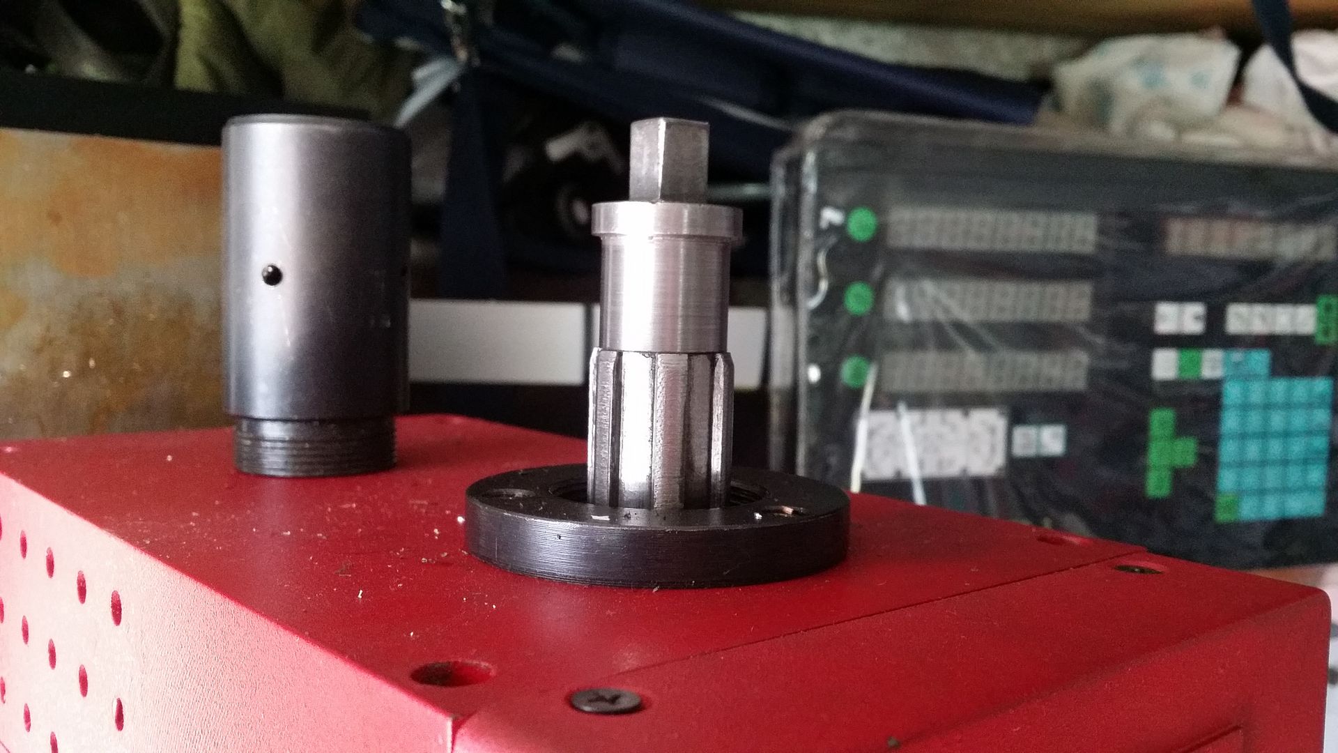
DIY arduino circuit boards optimized for electronic indexing head

Home Model Engine Machinist Forum

Help Support Home Model Engine Machinist Forum:

This site may earn a commission from merchant affiliate links, including eBay, Amazon, and others.
John, there is a much easier way to measure rotation. Just grab one of these https://www.sparkfun.com/products/11102

The link doesn't seem to work.
The stepper motor speed at 400 rpm is more than adequate, I wouldn't imagine a spindle speed over 250 rpm with a gear hopper, if you cut a 10 tooth gear, the indexer should rotate at 25 rpm, if the indexer is geared to the stepper at 5/1, the stepper speed would be 125 rpm.
I would not imagine the need for smaller gears as 10 tooth, and the larger gear, the slower speed.


Holt
 
Thanks Rod,

I'd seen the rotary encoder from sparkfun, but hadn't looked at it closely since it didn't look like there was an easy way to interface it with the mill spindle.

Yes such encoders output a square waveform that allows the controller to easily sense direction of rotation. Depending on the direction of rotation, the leading edge of the wave is either high and falls off, or is low and rises.

I recall reading that stepper motors have a limited maximum rpm rate so yes the hobbing set-up would have to be lower overall rpm within the maximum speed specification of the stepper.

Here is a good encoder tutorial with the interface programming.
simply attache directtly to the mill spindle
http://www.pjrc.com/teensy/td_libs_Encoder.html


cheers
 
Thanks Rod,

I'd seen the rotary encoder from sparkfun, but hadn't looked at it closely since it didn't look like there was an easy way to interface it with the mill spindle.
.

Just tap a thread on the inside of the spindle and screw in an appropriate adapter that attaches to the encoder.

EDIT: That might get in the way of the draw bar so on my SX3 you could attach it to the drive pulley in much the same way as the belt ratio can be accounted for in the software. I'd have to pull the top cover off again to see what the end of the drive shaft looks like.
 
Here is a good encoder tutorial with the interface programming.
simply attach directly to the mill spindle
http://www.pjrc.com/teensy/td_libs_Encoder.html


cheers

So this tutorial says the maximum speed the Arduino can handle is about 127,000 pulses per second. The encoder fires 4 pulses per step. I think the 200 step encoder from Sparkfun would be a better choice (and lines up with the resolution of most steppers).
https://www.sparkfun.com/products/10932

There will be 200x4 = 800 steps per revolution. So 127,000 / (200 *800) = 158.75 RPM maximum spindle speed. Lets say 150 rpm design maximum.

With a 90:1 rotary table, and assuming maximum design RPM of the stepper was 360 rpm, the fastest as standard RT can rotate is 4 rpm (360/90) unless you add some sort of geared drive. (I've seen some RT's driven by a timing belt ). I think this says you'd need to build a dedicated spindexer type fixture. I think my minimum spindle speed is about 90 RPM so a 10:1 ratio needs 9RPM on the RT.

If you assumed that the inertia of the spindle slowed the RPM enough so the software always caught up when the direction changed (pretty safe assumption I think), The interrupts just need to be modified to maintain the Direction of the stepper (DIR).

For simplicity, lets assume a direct drive and you want a 10:1 ratio, all the Arduino needs to do in the main loop is to check the encoder accumulator, you'd need something like this.
Code:
if(EncoderCount >= 10){
   DriveStepper(dir,  1);  // Output 1 step in current direction set by interrupt.
   EncoderCount -= 10;
}

This is way simpler than a dividing application. I think it would be best to be a dedicated Arduino for the task. Remember to use the timer interrupt to drive the stepper motor.....

Instead of frying your brains with math formula:fan: that I didn't wright maybe you should read what I sugjest
simply attache directtly to the mill spindle

This is only to help people. Maybe instead of puking on "my sugestion link" you should take your personal time and put an article on it
this would allow people to complaint about it
 
Instead of frying your brains with math formula:fan: that I didn't wright maybe you should read what I sugjest

This is only to help people. Maybe instead of puking on "my sugestion link" you should take your personal time and put an article on it
this would allow people to complaint about it

Luc, I made two posts. Clearly you missed my first post where I suggested how to attach the encoder. If ya gunna play with electronics, you have to know the limits before you start. Otherwise you could dive on the tools, do a lot of work and then find it won't work and end up with....:fan:
 
Instead of frying your brains with math formula:fan: that I didn't wright maybe you should read what I sugjest

This is only to help people. Maybe instead of puking on "my sugestion link" you should take your personal time and put an article on it
this would allow people to complaint about it

except cant be attached to my mill spndle since the drawbar is in the way.... and I have about 3 drawbars I need to use for different collets and boring head etc...
 
There will be 200x4 = 800 steps per revolution. So 127,000 / (200 *800) = 158.75 RPM maximum spindle speed. Lets say 150 rpm design maximum.

You got your math wrong, the 158.75 revolutions is per second, so 158.75 times 60 = 9525 rpm


Holt
 
FINAL Indexer Control Board Design - REVISED to be utilize a low cost Arduino Nano V3 rather than a arduino clone circuit.

The Nano plugs into a motherboard via 15pin female headers.

The motherboard name is "Arduino Nano Based Electronic Indexer v2.1"

This will be my final board design.

Input power between 6.5-12 VDC up to 5A.

5VDC Fixed Voltage Regulator board up to 800mA to power Arduino and accessories.

Optional Motor Supply Adjustable Voltage regulator board 1.25-36VDC, 0-5A output iin case the 12V regulated power supply is not suitable for your selected stepper motor.

Uses a Nano V3.0 with mini-USB connector connected to the main PCB via two 15 pin headers.

Features:
Main board +5V power input soldering pad or pin input options.
Motor Voltage input soldering pads,
Connector headers for lighted Keypad break-out board, IC2 LCD Display, and +5V & GND terminals for optional cooling fan and current sensor power.

Bill of Materials:
http://www.homemodelenginemachinist...o-based-electronic-dividing-head-v10-306.html

Link to Boards:

https://oshpark.com/shared_projects/NNEXkE31

https://oshpark.com/shared_projects/hcnykUxw

This final revision added the current sensor connector to the board, relocated and widened the 5V and GND traces on the board and added more room for the 100 uF motor capacitor. As soon as my boards arrive I'll follow with a detailed build log.

Front Nano index.jpg


Bottom nano index.jpg
 
You got your math wrong, the 158.75 revolutions is per second, so 158.75 times 60 = 9525 rpm


Holt

Thanks Holt. It was early in the morning and I was half asleep. Thats why its good to share. :eek:

The other side of the problem (being the maximum speed a stepper can run a 90:1 rotary table at) still stands at 4 rpm because I measured this speed with a digital tacho.

except cant be attached to my mill spndle since the drawbar is in the way.... and I have about 3 drawbars I need to use for different collets and boring head etc...

That may not be as hard as you think. Here's a pic of the drawbar on my SX3 mill. this is one I made.

20150202_123542_zpsqemazuct.jpg


It would not be too hard to come up with a way to connect the encoder to the drawbar via some sort of disconnect.

I know each mill is different, but I think it could be done quite easilly even if it required a dedicated drawbar with the encoder attached.
 
New Board Design

Input power between 6.5-12 VDC up to 5A.

5VDC Fixed Voltage Regulator board up to 800mA to power Arduino and accessories.

Optional Motor Supply Adjustable Voltage regulator board 1.25 -36VDC, 0-5A output if main regulated power supply is not suitable for your selected stepper motor.

Uses a Nano V3.0 with mini-USB connector connected to the main PCB via two 15 pin headers.

Features:
Main board +5V power input soldering pad or pin input options.
Motor Voltage input soldering pads,
Connector headers for lighted Keypad break-out board, IC2 LCD Display, and +5V & GND terminals for optional cooling fan and current sensor power.

.

I make my own board do you have the original file "eagle are what ever program you use"

Now am I missing something:wall::wall: why would you want to hook the encoder to your mill spindle :hDe: can't see the advantage

cheers
 
Now am I missing something:wall::wall: why would you want to hook the encoder to your mill spindle :hDe: can't see the advantage
cheers

It is to synchronise the speed at the mill spindle with the speed of the index spindle for gear hobbing, see the Youtube video in answer #38
It would be a very nice extra feature


Holt
 
It is to synchronise the speed at the mill spindle with the speed of the index spindle for gear hobbing, see the Youtube video in answer #38
It would be a very nice extra feature


Holt

Holt

I went back to the video these are not encoders but opto coupler allowing him to read GREY code with two of them to know if it goes forward or reverse and the third one to read the frequency or RPM.
you would send this signal to a steppermotor controler like this one
http://2.bp.blogspot.com/-DUMUZllDl...StepperMotorController+555+timer+circuits.gif
and you could control what you want at the rate you want in relation to your spindle speed and direction

steppermottor controllermod.jpg
 
That may not be as hard as you think. Here's a pic of the drawbar on my SX3 mill. this is one I made.

20150202_123542_zpsqemazuct.jpg


It would not be too hard to come up with a way to connect the encoder to the drawbar via some sort of disconnect.

I know each mill is different, but I think it could be done quite easilly even if it required a dedicated drawbar with the encoder attached.

Thanks Rod...

Your pic got me thinking...

I think I can to come up with something for the drawbar I use with my collet holders at least. Assuming there is sufficient length protruding above the retainer nut.

I assume I can make a coupler for each drawbar, some one is a hex head the other two are square head. But I've never made a square or hex hole in anything before let alone one that was concentric with another piece. I guess I'll have to get my brother to mill the holes.

Whatever I do I'll have to do away with the spndle cap and make a larger on that also acts as an encoder mount

2015-02-02_1509.jpg


2015-02-02_1507.jpg
 
That may not be as hard as you think. Here's a pic of the drawbar on my SX3 mill. this is one I made.

20150202_123542_zpsqemazuct.jpg

p.s. I like the pic of the kookaburra on your photobucket page.. reminded me of a song I learned when I was young... laugh kookaburra laugh...
 
p.s. I like the pic of the kookaburra on your photobucket page.. reminded me of a song I learned when I was young... laugh kookaburra laugh...


Hi do you have the original PCB drawing for your board
did you read the post I put here about the EMC 2 the guy is using in post 38
 
Holt

I went back to the video these are not encoders but opto coupler allowing him to read GREY code with two of them to know if it goes forward or reverse and the third one to read the frequency or RPM.
you would send this signal to a steppermotor controler like this one
http://2.bp.blogspot.com/-DUMUZllDl...StepperMotorController+555+timer+circuits.gif
and you could control what you want at the rate you want in relation to your spindle speed and direction

How would you control the stepper speed 100% with that?
If it takes lets say 10 minutes to cut a 50 tooth gear, if the stepper is off by half a revolution by the end of that time, you end up with a helical gear in stead of a straight cut, that kind of precision can't be achieved with a potmeter.


Holt
Holt

check this video you will understand more This is how weve been controlling robots and close loop CNC for years

check the speed also


http://www.pjrc.com/teensy/td_libs_Encoder.html
 

Latest posts

Back
Top