Rod's Aussie Shed

Home Model Engine Machinist Forum

Help Support Home Model Engine Machinist Forum:

This site may earn a commission from merchant affiliate links, including eBay, Amazon, and others.
A bandsaw is on my wish list of machines, I will keep a note of this model, I have seen them at Machinery House (H &F).

Paul.

Paul, the BS5 that Cam and I both wore out is on special ATM at $385 so you would never get a cheaper saw than that right now. That was what I was planning to buy but H&F had this one there for $495 so it was a no brainer to spend the extra $100.

I think in my case, the motor burned out out because of problems in the gearbox and bearings as it was siezing intermittently for a while.

Add a filler bung to the BS5 gearbox and maybe put a perspex cover on it to see the oil level and for home use, it will last a long time. Mine had done a lot of work, sometimes running 8 hours a day, cutting 8 metre lengths down to 55mm pieces and I still got 5 years out of it.

Its a shame that H&F don't fit a hydraulic descent cylinder to the BS5-S that I just bought. You can see an undrilled spiggot in the yellow casting just below the depth gauge to fit one to. Based on what I have seen elsewhere, the other end of the cylinder would go to a bracket mounted using the gearbox cover screws. If anybody knows where to get a cheap cylinder from, please let me know. A $35 part in the US becomes a $200 part down under. :(
 
I burnt my out buy leaving it going wile I came in for a drink and started talking. by the time I got back to the shed all was quite and the lights wore out I must say it took me a wile to work out it was the saw with a short piece of about 2 inch bar jammed between the stop and the blade. I never leave the new saw cutting with out being near it. cam
 
  • Like
Reactions: gus
Well, I bought a 5C collet chuck from Little Machine Shop and started to mount it up today. For the Aussies, I went to George Weston and Sons and bought two 30mm wide slices of 165mm diameter round grey cast iron which cost $33 each. They have a huge range of cast iron and brass stocks.

I have fitted a chuck before and decided that I needed to be precise when dealing with collets so I decided to make a plug as a guide for this chuck and any other chuck I might fit. I got out my barely used 4 jaw chuck and indicated in the rough cast iron as best I could. I faced it off and then machined a 5mm high boss that was a snug fit to the back of my 3 jaw chuck. In theory, this should be an exact copy of the spindle mounting plate.
20140618_154520_zpscbwxs3e9.jpg


I have left it in the chuck overnight to have a think about things but the idea is to chuck up the other piece of cast iron, face it and machine a matching recess which mates snugly. I will use this plug to check the dimensions. Last time, I just shot for the measured dimensions but this more complex method should give me the confidence and tools to get a much more precise fit which hopefully will keep runout to a minimum. I might centre drill this piece so I can find the centre again if I ever need to.

Stay tuned!
 
Hi rod I am looking at the 5c collets for my new al336d lathe when it turns up. I have been using mt3 collets and er32 collets in my al50 and love them. Where did you get you collets from?
 
Hi rod I am looking at the 5c collets for my new al336d lathe when it turns up. I have been using mt3 collets and er32 collets in my al50 and love them. Where did you get you collets from?

Cam, I got my Imperial 5C Collets (and the chuck) from Little Machine Shop in the US and my Metric ones from CTC in Hong Kong. I have since found a supplier on Albaba who sells them all including Hex and Square (metric and imperial). He says minimum order is 100 pieces but I have heard he will accept a sample order.

I was going to stock up once the coffers refill.

If you are interested, I think I will have a spare, hardly used Hare and Forbes 5C Collet Spindle kit and a handful of unused metric 5C collets that somebody gave me (but I bought a complete set soon after) once I get my chuck sorted out.

EDIT: Here is the link to the supplier above


http://dzdrjj.en.alibaba.com/productgrouplist-214632782/5C_COLLET.html
 
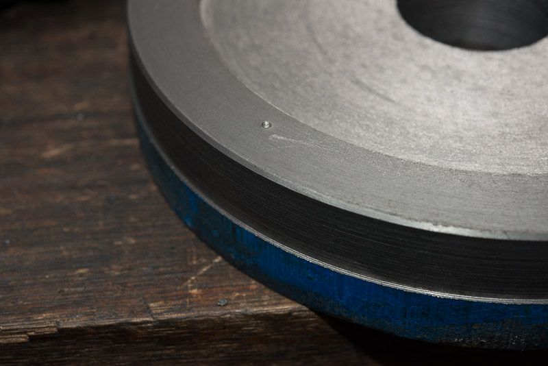
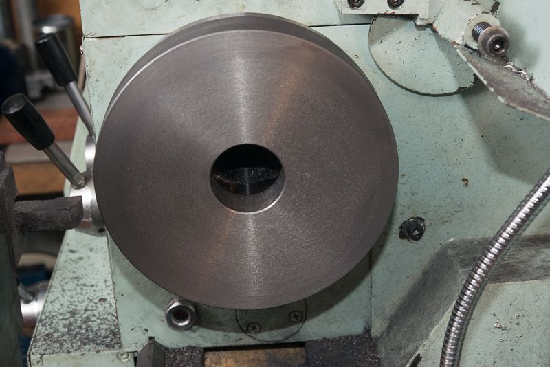
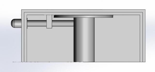
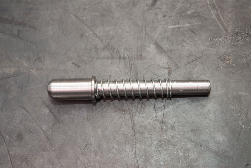
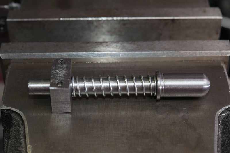
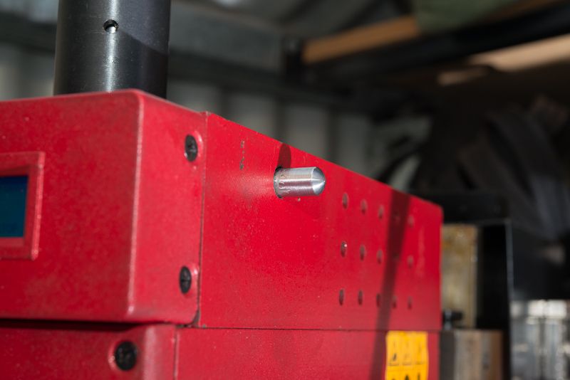
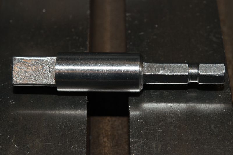
Well, I got my chuck fitted up late this evening. Following on from my cr@ppy phone photo, this is what I came up with for my master pattern.

This is now my master for any other chucks I fit to this lathe. I am so glad I took the time to make this as it made everything so easy! None of the heart in mouth stuff wondering if it will fit as planned when you take it off your spindle!

DSC_5051_zps5cf85b6d.jpg


The next chuck I fit will just be so easy now I have made this up.

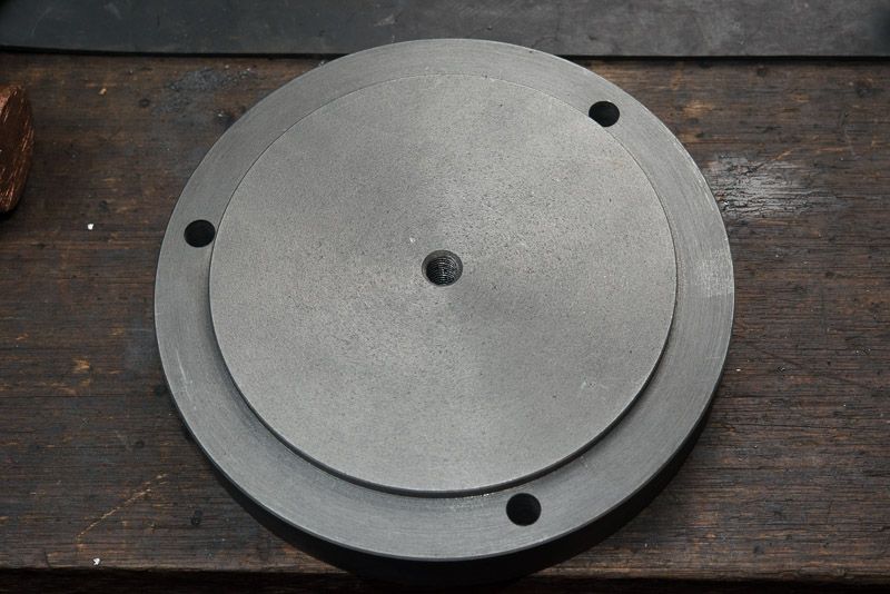
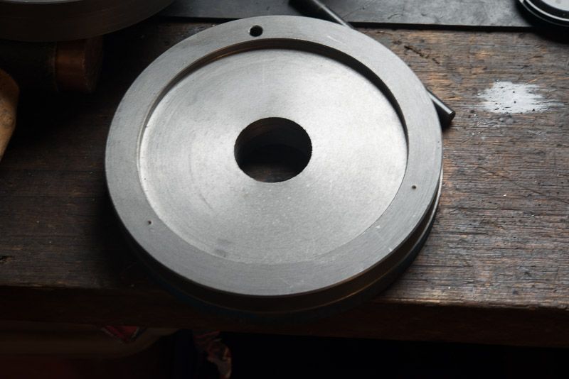
This is an exact copy of the lathe spindle mounting flange (but a bit thicker). As stated yesterday, I held this in my 4 jaw chuck an fitted this up snug to the back of the 3 jaw chuck, turned it over and faced the back side and tided it up. While it was in the chuck, I decided to drill the centre as I would ever get another chance and for some reason, I decided to drill and tap the hole so I could use a transfer screw at either side if I ever needed to mark a hole in another piece and I could still use that as a precise reference of the centre.

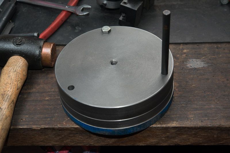
The next step was to install some transfer screws in the back of the 3 jaw

DSC_5053_zps1c52a969.jpg


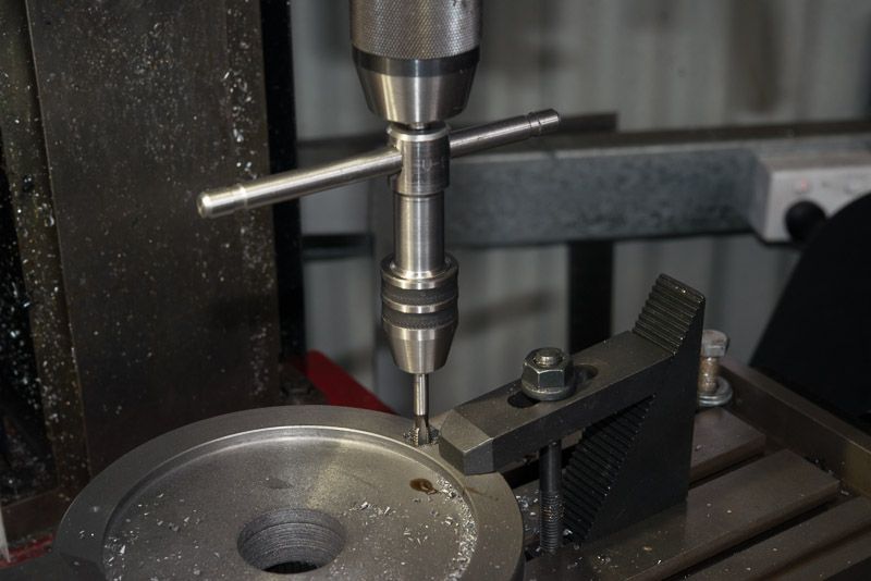
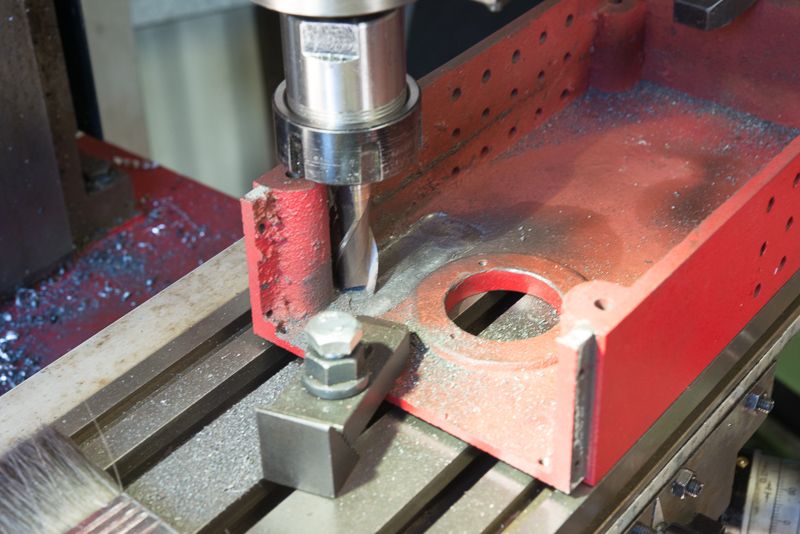
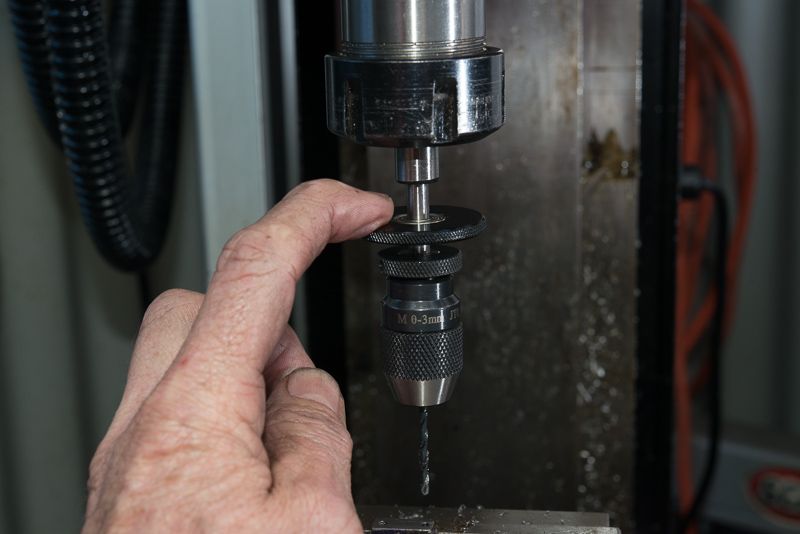
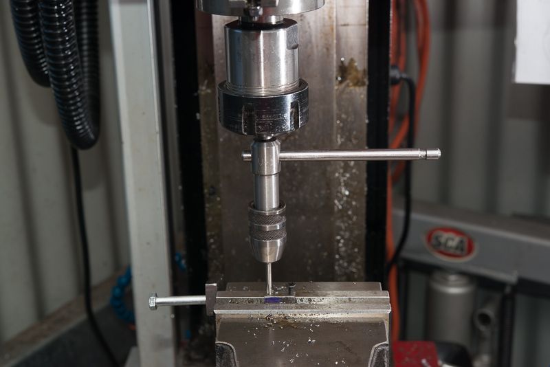
and fit this template up to it. One quick bash with a hammer and I had 3 nice centre punch marks. Then it was over to the mill and I drilled the three holes starting with a 3mm pilot hole that lets me see the drill flex and bend as I line it up in the centre punch divot.

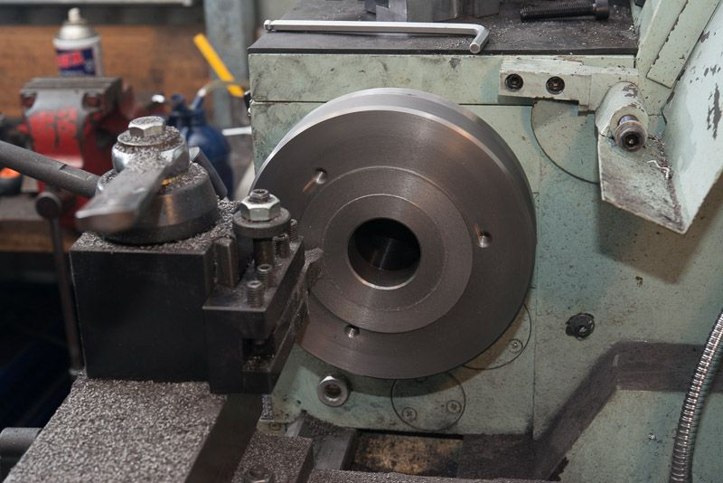
So with the template done, I chucked up another piece of cast iron in my 4 jaw and machined a recess that was an exact match to the template boss. Once I was happy with the fit, I left it in the 4 jaw chuck (heavy as) and unmounted the chuck, so I could check fit on the spindle boss. I figured if it was not right, I could just bolt the chuck back on again. I nednt have bothered, It was a beautiful fit!.

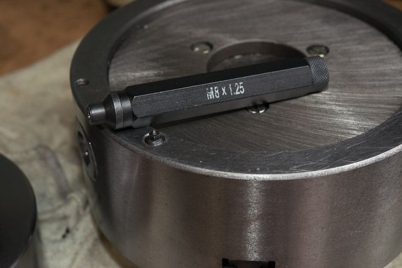
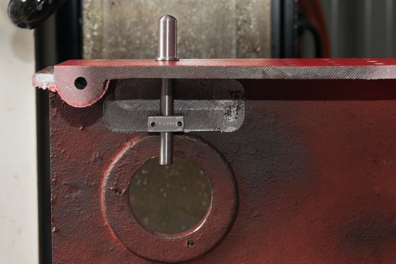
Now over to the bench and I fitted up my template and grabbed a transfer punch (not a screw this time).

DSC_5041_zps67a8bb6d.jpg


I punched drilled and tapped one hole and with the two pieces held together so nothing could move as shown above, I punched the other two hole positions.

DSC_5044_zps56253548.jpg


DSC_5042_zps8b0a0adc.jpg


Back over to the mill to drill and tap the other two holes

DSC_5047_zps8deec4f8.jpg


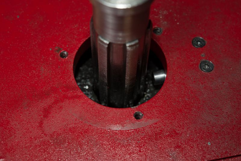
Finally starting to make progress! One piece of cast iron bolted up to the spindle!

DSC_5049_zps7beed8dc.jpg


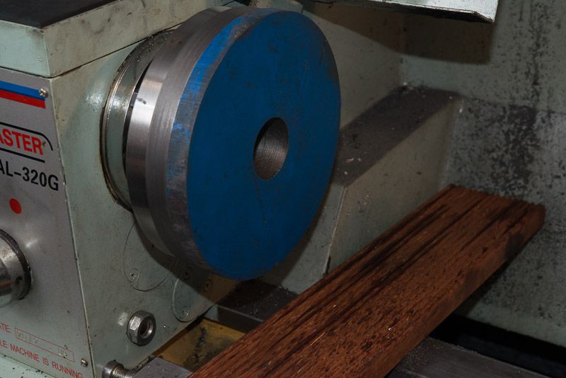
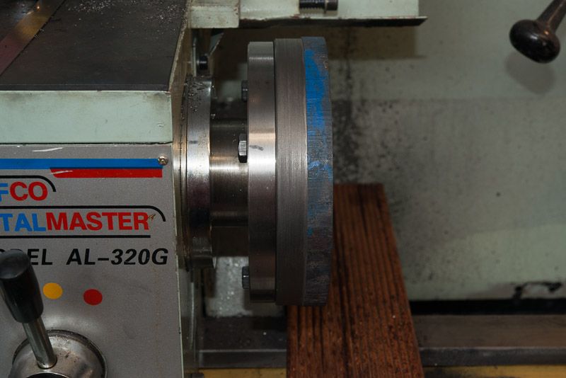
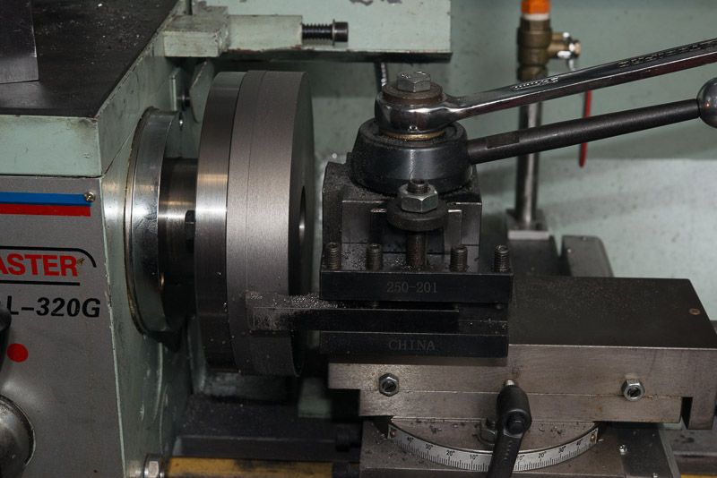
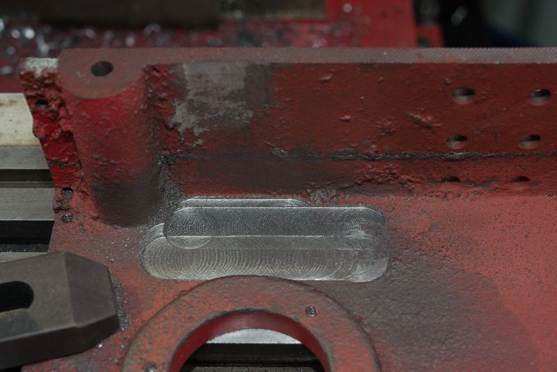
In the earlier setup, the piece was held in the 4 jaw chuck so I could not machine the outside diameter. The blue paint is how the material came from the supplier.

DSC_5050_zps6b65cb42.jpg


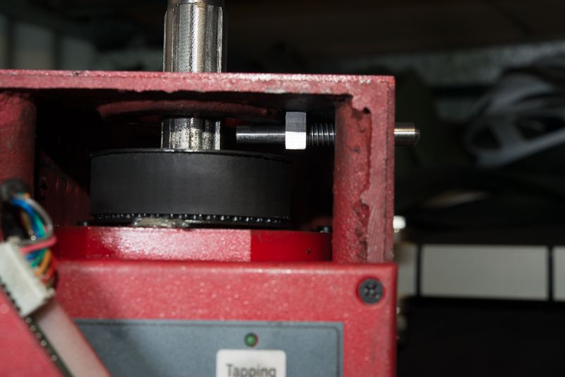
This pic also shows one of the mounting bolts that goes through the spindle flange and screws into the backing plate I made.


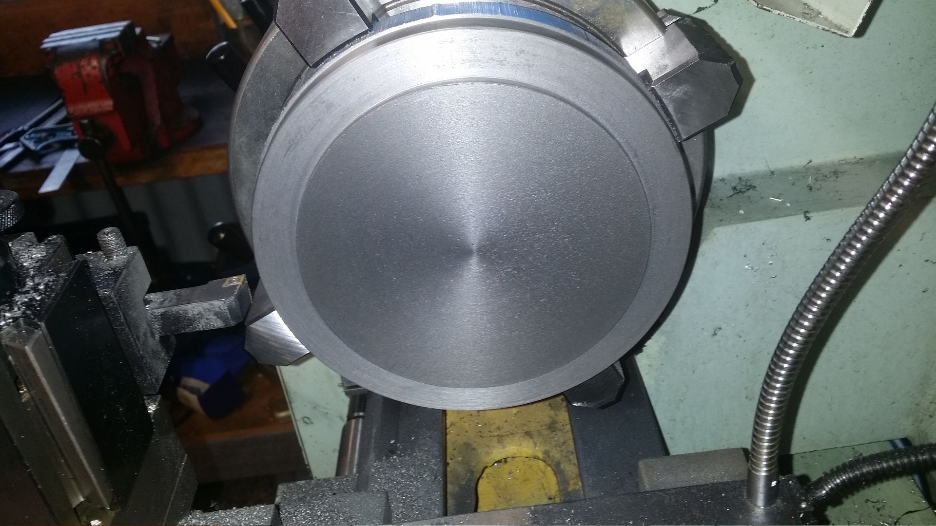
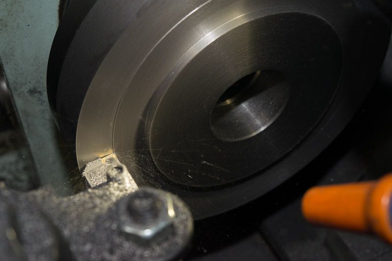
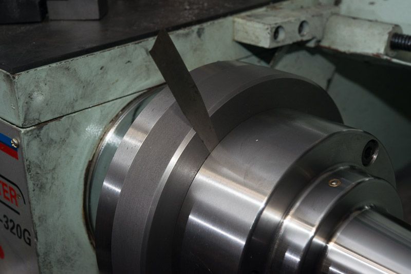
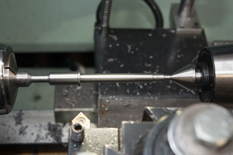
So from here, the next step was easy. Face it off and tidy it up. I skimmed the hole in the centre again so it was machined in its final position.

DSC_5054_zpsf0c5d7f4.jpg


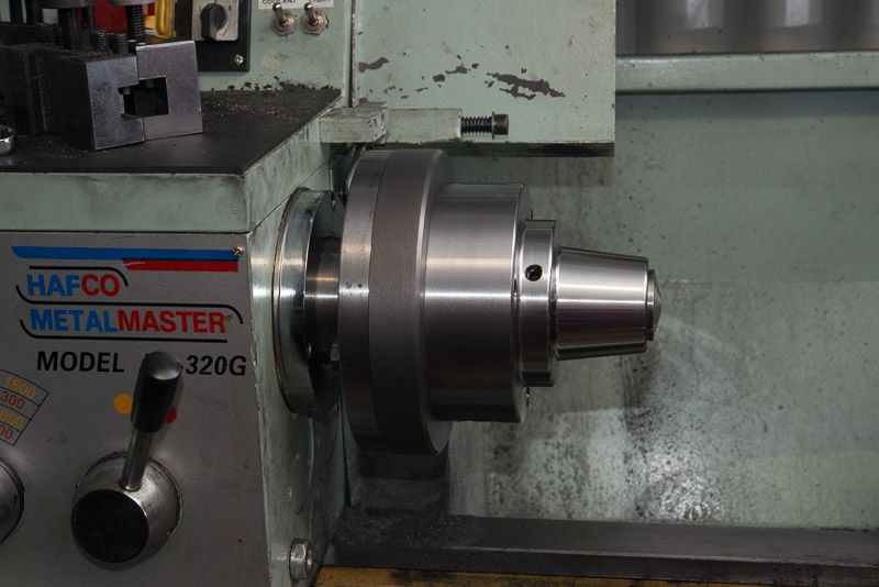
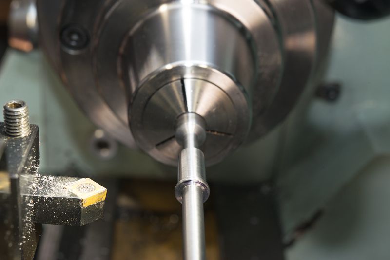
Then machine a tight fitting 95mm boss to fit the back of the spindle chuck.

DSC_5057_zps8fe98108.jpg


Fit the transfer screws to the back of the collet chuck to mark the holes
And head over to the mill again, repeating the previous process to drill and tap the threaded mounting holes on the front of the backing plate.
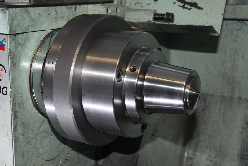
And bolt it up!

DSC_5067_zps3e677d7d.jpg


DSC_5060_zpsa44a2b8b.jpg


Look how dirty my lathe got with all this cast iron!

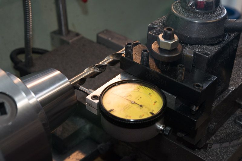
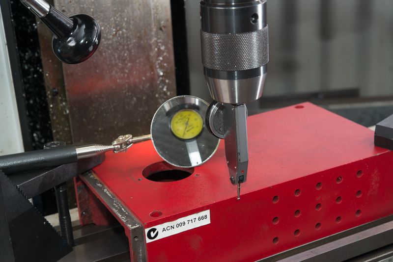
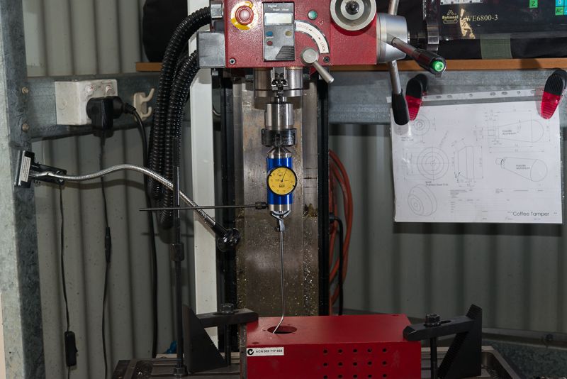
I had run out of time by now and a quick check of the runout (0.10mm or 0.004" TIR) was a bit disappointing. I thought I could see a slight gap at the back of the collet chuck so I went inside and found a drawing of the chuck on the Little Machine Shop web site. Sure enough, the drawing showed the recess was 4mm deep. I had measured it at 5mm and set the height of my boss to be 4.8mm so I think a quick adjustment in the morning will fix it. There is zero runout on the backing plate I machined and the registers on the back and front of the backing plate are perfect so there is no reason for this chuck not to be concentric due to anything I have done! Wish me luck tomorrow!
 
Ooops, I missed one photo. I had to turn a few things inside out to machine the outside diameter to size.

DSC_5056_zpsa0f566da.jpg


You can see, I swung the tool post right round and had to reverse the tool in the holder to match the job at hand.
 
Had a quick look at the chuck again scratched around for my feeler gauges which have not been used for over 30 years since the stopped putting points in cars. I soon found the reason for the runout I saw last night.

DSC_5069_zps6aafa792.jpg


The gap was 2 thou. (Yep my feeler gauges are so old, they are imperial!)

As suspected, I had made the boss too high so I just skimmed a bit more off the top.

DSC_5074_zpse661fdcb.jpg


I played for a while and found that the way you tightened the bolts securing the chuck to the backing plate made quite a difference.

Then I put a 12mm drill in a collet and put my best dial indicator onto the job.

DSC_5076_zps62fbea67.jpg


Measured 0.01mm of runout! That is 0.00039" TIR.

How good is that for a rank amateur? I am happy as!

I think I will call this job done!
 
A job well done Rod, I could hear your sigh of relief down here in Melbourne when you finally checked the runout.

Paul.
 
(Yep my feeler gauges are so old, they are imperial!)


Hahaha! careful our friends in the USA will have a piece of you for that comment.

Nice job there, Silently following along still.

Baz.
 
(Yep my feeler gauges are so old, they are imperial!)


Hahaha! careful our friends in the USA will have a piece of you for that comment.

Nice job there, Silently following along still.

Baz.

Baz, the scary thing is back in the late 70's when I bought them, I actually thought in imperial! :eek:

Now I refuse to buy a tape measure or ruler with inches on it!
 
This thread has given me some Inspiration.
http://www.homemodelenginemachinist.com/f13/siege-super-x3-mill-mods-3611/index2.html

I spent a couple of hours looking for options for a spindle lock on my SX3 Mill. Google led me back to this forum. I liked the simplicity of the brass button approach on this thread but the SX3 needs a different approach.

I spent some time today designing a SX3 version which needs to enter from the side. It doesn't need a circlip because it is about 65mm long and will need a guide to slide through that will retain the spring. Hopefully, I will make a start on it tomorrow. I gotta find an excuse to use my collet chuck!
 
This is a rough drawing of what I have in mind viewed from the front of the mill.

MillAssembly2_zps42f77302.jpg


I will turn this out of 12mm bar stock. The button will have a 10mm dia head on it and a 12mm dia flange on the inside of the case so it can't pop out. The shaft is 7mm which is the same width as the slots in the flanged spindle (which is only roughly drawn).

The smaller shaft will pass through a bracket secured from above with some M3 countersunk screws in the top of the mill cover. the only tricky bit will be to get the height of this part right it is level with the hole in the case.

I have not drawn it, but I will fit a compression spring on the left hand side of the bracket to keep the button away from the spindle until it is pressed.

After a bit more thinking, I will probably fit the lock on the opposite side of the drawing as I am left handed.

I like the simplicity of this idea but if anybody has any suggested improvements. please post them up.
 
Well, this is slowly coming together. It's gunna be sweet!

So my first job with my collet chuck.

DSC_5078_zps09c38c8c.jpg


I turned each end down so I could get my tools in there. I used a neutral tool shown to get clearance then used left and right hand turning tools to get a nice square edge to the flanges.

awesome Chuck!

DSC_5079_zpsb002a3a4.jpg


The finished locking pin. I used my ball turner to cut the radius.

DSC_5082_zps6c8b383c.jpg


Time to clean up the casting and make sure there is a milled surface to mount the support to and the side is relatively smooth for the button flange to seat against. After it is milled, use the DRO to measure how thick the casting is by comparing the height of the milled surface to the mill table and note the measurement as we'll need it later. (mine was 6.25mm)

DSC_5083_zpsc9f3ab2b.jpg


Yup, the head of the mill is naked for now but still runs even if the spindle tacho display is hanging loose by the wires.I had to use a big end mill to reach the bottom when I cleaned up the side.

Baz, I was in shock! it was an imperial end-mill! And only because I got a good deal on a set from an online auction AND they sent me the wrong set! They could not fix the problem by replacing them with metric ones per the listing so they were very cheap after I gave them a piece of my mind.

Finished inside.

DSC_5085_zps45d390fc.jpg


You can see there are a few rough bits in the side of the casting that might need cleaning up.

Now to make the support. I cut it from a piece of 8mm flat bar Mild Steel. Measures 14mm x 18mm. The two mounting holes are 2.5mm from the edge (13mm apart). A good excuse to use my new Sensitive feed drill chuck from LMS. I tried to buy one from the ages ago but they were out of stock.

DSC_5087_zpse57c83e1.jpg


I bought a used one off ebay but never really got it working as it was not in good order. As they were back in stock, I added one to my Collet Chuck order. If you have not seen one before, you pull the chuck down with your fingers so you don't break a drill. Probably did not need to use it for a 2.5mm hole, but I had to find out how good it was.

Tapping 2 x M3 holes. You can see a countersunk screw in one hole

DSC_5088_zps9cbc9188.jpg


Where I got to today. Hopefully I will finish it on Saturday if Camo does not distract me too much as he is dropping round when he picks up his new lathe!

DSC_5089_zpsaee73ea3.jpg


It took a bit of figuring to get the clearance for the locking pin over the boss in the middle of the cover. In the end, I put a parallel across the cover and measured the difference in height between the milled section and the top of the boss. I aimed for about 1mm of clearance between the pin and the boss and drilled a 7mm hole in the support that the pin will pass through. For my mill, the hole was 7.5mm from the edge of the support that mates with the cover.

So there is not much left to do. The plan is to clamp the mill cover down on the table red side up, indicate it parallel and find the X&Y edges. Then I will use a Coaxial centring gauge to locate the centre of the hole for the spindle and note the measurement. Then I will drill and countersink 2 M3 holes to mount the support so the locking pin will hit the spindle dead centre eg. The mounting screws just need to be in the milled section and straddle the spindle centre line. All I will then need to do is to set the cover up on its side and drill a larger hole for the button at exactly the right spot to line up with the support. That is why I measured the thickness of the cover. The other coordinate will be centre of the hole noted earlier.

I hope it works!
 
Well, I finished this off. And it works!

I had to indicate the front edge based on the measurements I had so I was glad I remembered I had a mirror to read the scale.

DSC_5092_zps8e1eb472.jpg


Next step was to find the centre of the hole the spindle passes through using a coaxial centreing gauge. This is an awesome gadget when you get your head around it. You can see I mounted a post from my clamping it to stop the dial from spinning. First, rotate it above the hole to get it pretty well centred. Then with the spindle turning on slow speed, adjust the x table to minimize the dial movement. Do again for the Y axis an you are done. repeat if desired.

DSC_5095_zps5c8f5742.jpg


And check the pin actually lines up with the support we added.

DSC_5098_zpsf3dd6ef6.jpg


Much happier now.So time to fit it and screw the support down.

DSC_5099-Edit_zps30960bc8.jpg

Awesoe! it does

You can see the end of the pin in this shot . I trimmed the length to suit at this time.
And here is another shot with verything mounted in position

DSC_5101_zps6cc97bbf.jpg


And the finished job.

DSC_5102_zpsd72895fd.jpg


How neat is that?
 
Ok, that's clever and my x3 seems to need one more modification :rolleyes: Only worry I can see, is it strong enough? Maybe I'm only one with over thigh tendency.

I am pretty gentle tightening the drawbar, the casting is 6mm thick, so I doubt you cold break it! If there is a problem it will be because I used M3 screws not M4 or M5, but that was the size countersunk bolt I had. I think if the end of the pin was tapered at the same angle as the spline, it might be a bit more secure. I had to oversize the outer hole a bit to get the button in (which adds a bit of play), so keep the thick section of the button as short as you can and maybe keep 1.5-2.0m clearance above the boss in the casting (but be mindful of clearance with the pulley below the pin).
 
Here is a great addition if you have a collet chuck and an electric drill. It is also a great project for a collet block set.

DSC_5105_zps676b8ae6.jpg


DSC_5107_zpsba1f17a6.jpg


If you have not used a collet chuck, you might not know that uing 5C collets involves a lot of chuck spinning so now I have the fasted collet chuck key in Australia! :)

I must say, this works great!

Pretty simple really, start with a piece of 1/2" or 12mm bar (which I used) but you get to use both the 4 sided and six sided collet block. After cutting the Hex shaft, rechuck it and cut the groove. I used a 60 degree Neutral tool.
 
Thank you rod for an interesting thread.I know its old but I have just finished rereading it all and have added this comment to bring it back to the front
Perhaps you can let us have an update. Regards Barry
 
Thank you rod for an interesting thread.I know its old but I have just finished rereading it all and have added this comment to bring it back to the front
Perhaps you can let us have an update. Regards Barry

Barry, Thanks for the comments. I'll have to see what I can do to add a bit to this when I get a chance for your reading enjoyment :)

Currently, doing a bit of a garden makeover outside the shed so time is precious. Every shed should be surrounded by landscaped gardens don't you think?
 

Latest posts

Back
Top