Ignition circuit help

Home Model Engine Machinist Forum

Help Support Home Model Engine Machinist Forum:

This site may earn a commission from merchant affiliate links, including eBay, Amazon, and others.
The weekend before Autorama is the busy time. A good friend of mine has a sheet metal shop, and gets a significant amount of last minute business up until Wed night for move in.. Of course, he got more of it when we were building his cars to that same deadline. :mad:
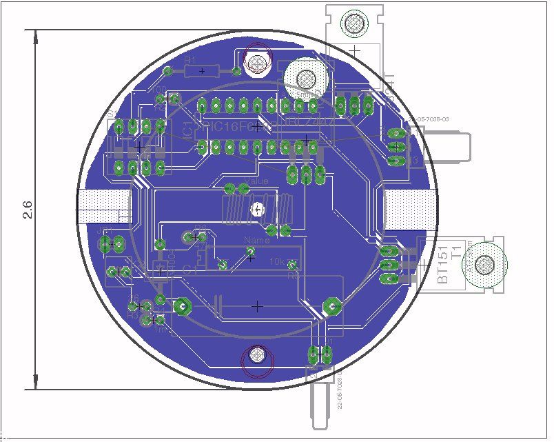
Lest I digress too much about old racing days, which are much better conversations to have in person over an adult beverage, tonight's goal is to have MkII soldered together on a pair of circuit boards. Debugging is basically done and board design for emf protection is next.
MkI is still available for trials if you have an itch. Sat afternoon I have an engagement but remainder of weekend is for getting things accomplished. 96/Inkster.
 
The circuit you posted is a poor variation of the "old school" TIM circuit. A hall sensor in theory will activate it but the resistor values on the front end are pretty low value and depending on the sensor it might not be able to drive the circuit and/or may damage the sensor. The problem with all of the original TIM circuits is the output transistor breakdown voltage. In order for a coil to work properly you must not supress the kickback voltage generate on the primary side of the coil when the "points" open. When you use conventional points there is no problem since the points gap is quite large.
In the case of the TIM circuit the transistor breakdown voltage is perhaps (unchecked for the particular transistor) 150volts at most. This will limit the seconday Hi voltage to 150v x the turns ratio of the coil. Typical turns ratios are about 100:1 therefore the secondary will only get to 15kv. That's probably more than enough for a model engine but you can do better.

Try my circuit below. It has the following improvements:
1. The front end is designed for a Hall sensor.
2. The first stage does not sit around consuming a lot of power when the engine is not running. The circuit you presented consumes considerable power just sitting there doing nothing.
3. A big problem with all of the TIM circuits was that it was possible for the engine to stop with the ignition activated which could (usually did) burn out the coil and or transistor or both. This circuit will not do that.
4. Most important is, this circuit uses a proper IGBT transistor to drive the coil. One that is made specifically for this purpose for automotive ignition systems. It has a very high breakdown voltage.
5. A little extra benefit is the LED which blinks when the Hall sensor is activated so you can tell if there is activity.
6. The input circuit can be run on the same 12v as the rest of the circuit but need not be. Just be sure the ground is common to both supplies.
7. And the best part - the IGBT is a logic level input device so, if you are so inclined you can elminate the front end altogether and drive the IGBT base with a microprocessor or logic chips.

Note that the symbol for the IGBT transistor is not precise. It's drawn like it is to make if familiar to the original circuit. The IGBT is a TO220 device so you'll need to consult the spec sheet to get lead orientation.

With a little ingenuity you should be able to use your existing circuit board by leaving out components and perhaps cutting traces and adding jumpers.


[EDIT Feb. 22 2013]
Updated drawing. I had the wrong part number variant for the IGBT transistor. Sorry. All is correct now.

Sage

Sage,

I didn't appreciate how good your circuit was until I sat down to design my own. When I first looked at it (and commented - incorrectly) I didn't notice that you were using an IGBT (since it's drawn as a BJT). That would've grabbed my attention for sure!

I then I forgot all about it! Including my remark about AC coupling the input to prevent the battery from being drained (and coil potentially cooked) if the engine stopped with the coil stuck on. Ugh. My short term memory is cooked... I could have saved myself quite a few hours of design time.

Now that I have my circuit under my belt, I am surprised how close my input circuit is to yours. Then again, there are only so many ways to skin a cat.

I think the only advantage my circuit has is reduced power consumption. My design doesn't need to draw current to keep the output IGBT off.

My circuit is posted here: http://www.homemodelenginemachinist.com/f31/new-ignition-circuit-20415/index2.html#post214570

Cheers!
John
 
Great minds think alike I guess.:)
I posted a couple of comments / questions on your other thread.

Sage

I don't see any posts from you in that thread. I'm curious what your comments and questions are...

Bear in mind the circuit hasn't been built yet. Still waiting for parts from Digikey. While it simulates fine in PSPICE, I learned that PSPICE often lies!

My main concern (that may be too strong a word) is the values of the resistors in the input network. I'm not 100% convinced PSPICE is modeling the Hfe of Q1 correctly for saturation. I don't have my old Motorola databook here at home which has all of the related info (overdrive factor, hfe vs Vce etc) - stuff that's no longer part of datasheets today. Why, I don't know....

Thanks!
John
 
Check out the TC4426 /27 /28 from Microchip. It's a dual high power (1.5A) MOSFET gate driver. I've used those. They work really well. Does away with all the discrete stuff. But then that's another 8 pin DIP component to add to the design.

Sage
 
Check out the TC4426 /27 /28 from Microchip. It's a dual high power (1.5A) MOSFET gate driver. I've used those. They work really well. Does away with all the discrete stuff. But then that's another 8 pin DIP component to add to the design.

Sage

Those a great IC's. I've used them a lot! Also the 4424 and 4425 drivers. The nice thing more me is that Intersil makes them radiation hardened for space electronics.

The other IC I like to use is the International Rectifier IR2113 dual high/low gate driver IC. That bugger allows you to use identical N-channel MOSFETs in a totem pole.

John
 
OK here is the deal


Untitled.jpg
Still trying to figure this out, those dimensions dont quite add up. Whats the bolt circle diameter and size?
 
boardv1.jpg

I think I can squeeze it in, but its gonna be tight. A 1uf cap at 450v is not a smd component, and neither is the 1.25" toroid I am using at present. :( The depth is almost certainly going to be a violation. I will see if I can get a board made today or tomorrow.
 
boardv1.jpg

I think I can squeeze it in, but its gonna be tight. A 1uf cap at 450v is not a smd component, and neither is the 1.25" toroid I am using at present. :( The depth is almost certainly going to be a violation. I will see if I can get a board made today or tomorrow.

Will you post the circuit on here or make it availlable to member
 
Will you post the circuit on here or make it availlable to member
If I ever get the design down to a science instead of a "black art" its possible I might sell them. Flyback transformers at this voltage level are pretty touchy, and parasitic capacitance effects make it unlikely to be an easy project to complete as published.
 
I have another coil here, 1 of a 3 pack for GM distributorless ignitions. It gives a hell of a spark and should be an easy replacement on your engine if need be. I dont have any real doubt that you have a CDI style coil, and this should spark it just fine.
 
Finally, not too shabby. My first attempt at a genuine photoresist board. Bought the boards two years ago as emergency stock, my guess is the chemicals were at least good enough. Ran out of toner, had to ebay that, and some transparencies as well, and had to wait all week for them to arrive. Mcmaster provided a yellow darkroom bulb, a nice piece of 1/4 thick glass to hold everything flat, and the local home depot provided a grow lamp bulb for the exposure. Then, a last minute dash to Meijer for a container of lye to use for developer, cut the bottom off the board and made an exposure test strip. 13 minutes later I settled on a 6.5 min exposure time, and for what seemed like hours rocking the thing back and forth in FeCl I have this!

Tomorrow morning we drill, populate, and test it out.
 
Nice board Thm:
there is a much easier way and the outcome is even better
instead of using transparencies simply use real photo paper in a lazer
printer then a few minutes under the iron to transfer your drawing and you etch
the results are crystal cleer and you dont have to worry about day light
 

Latest posts

Back
Top