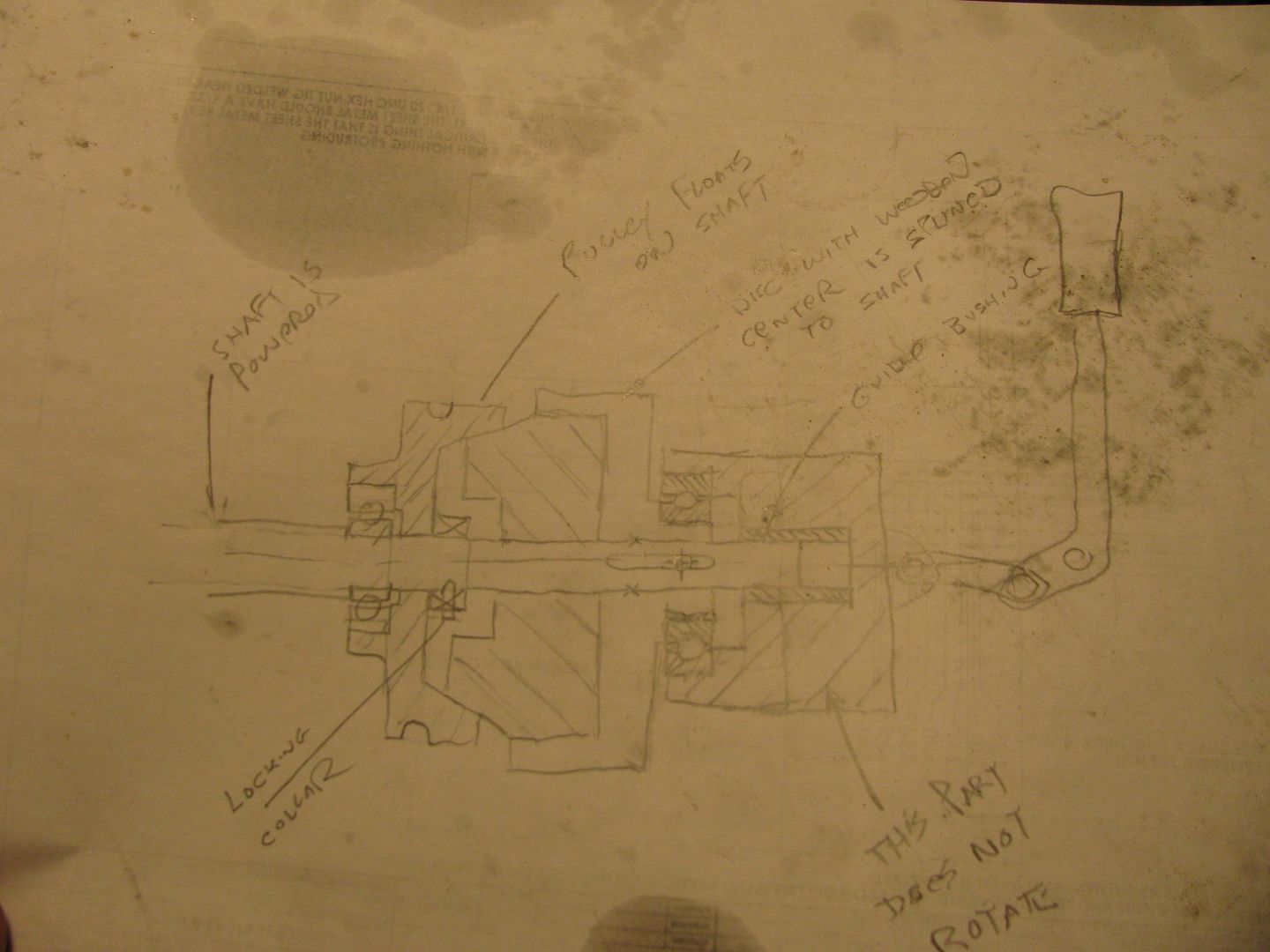
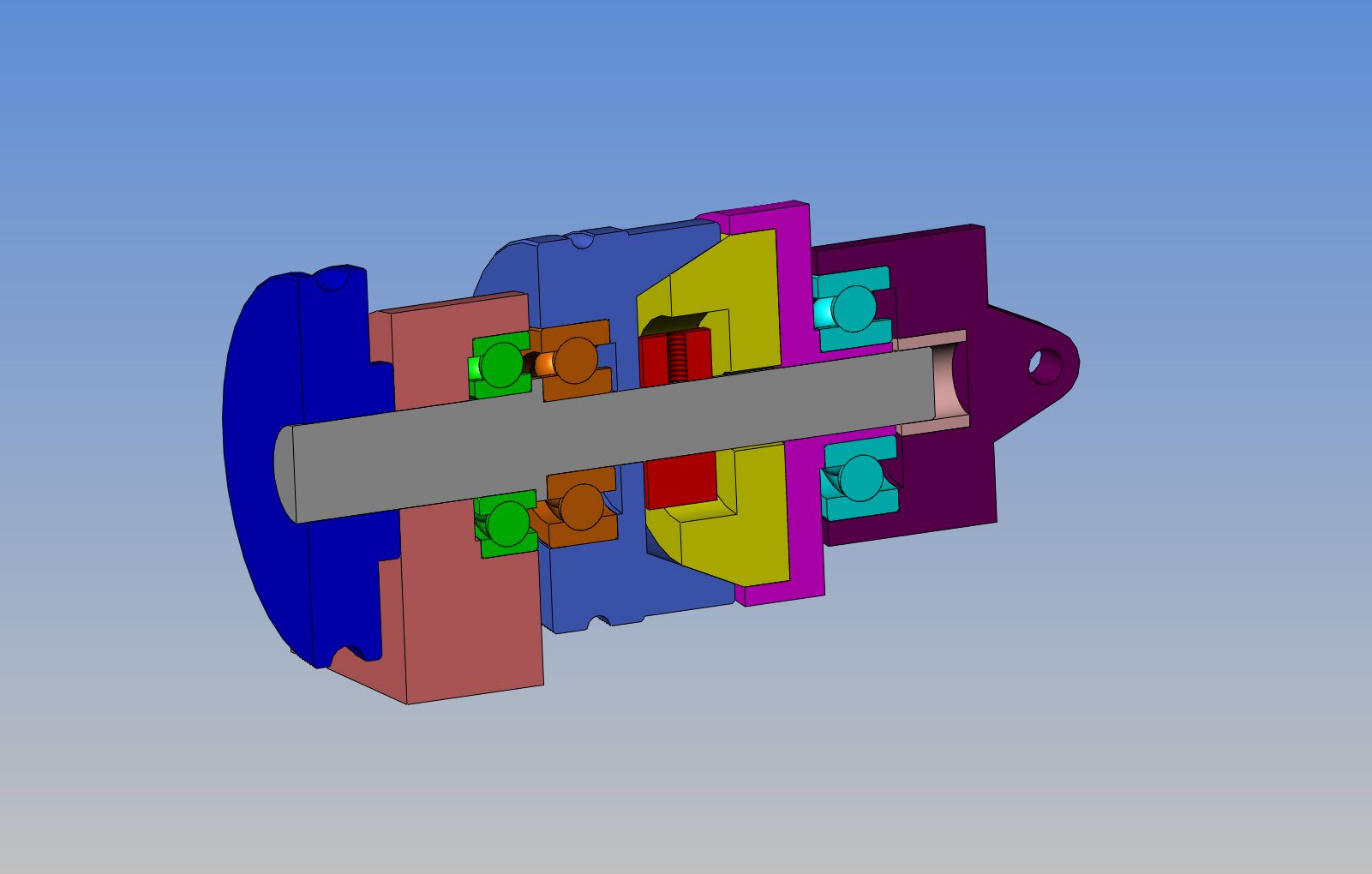
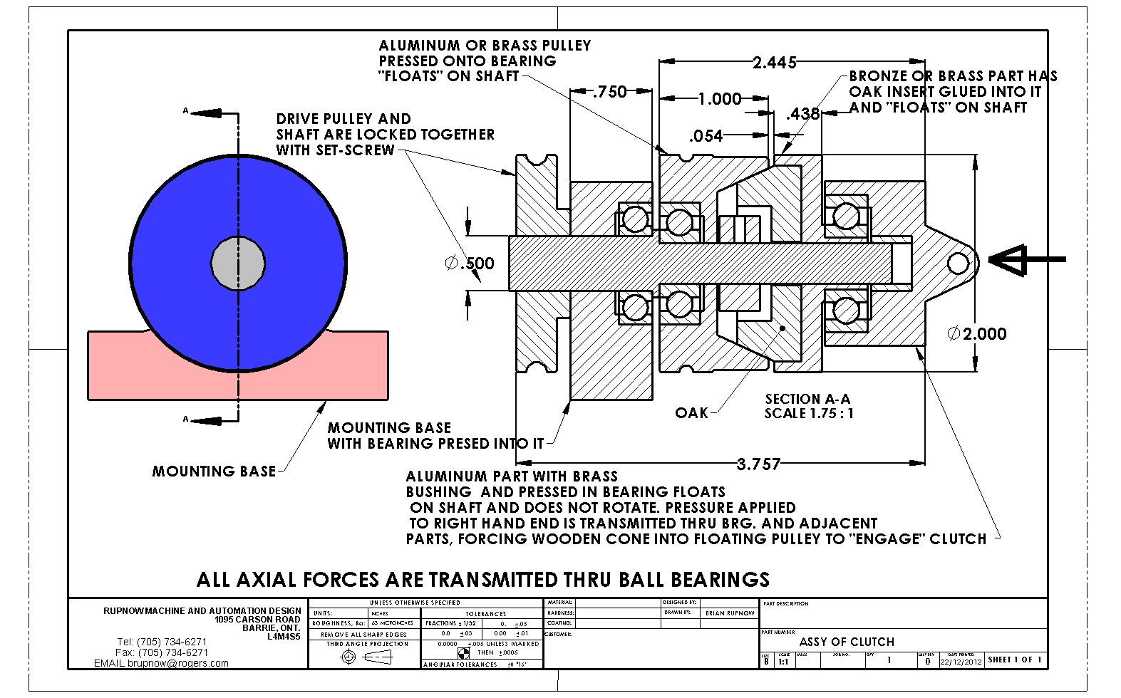
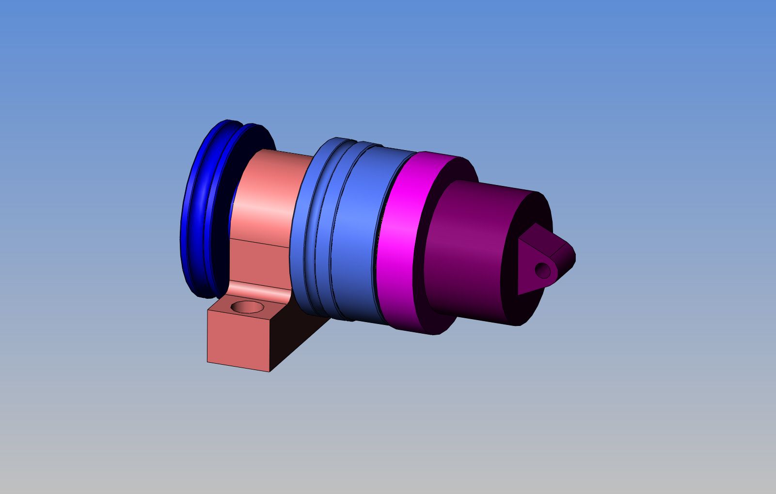
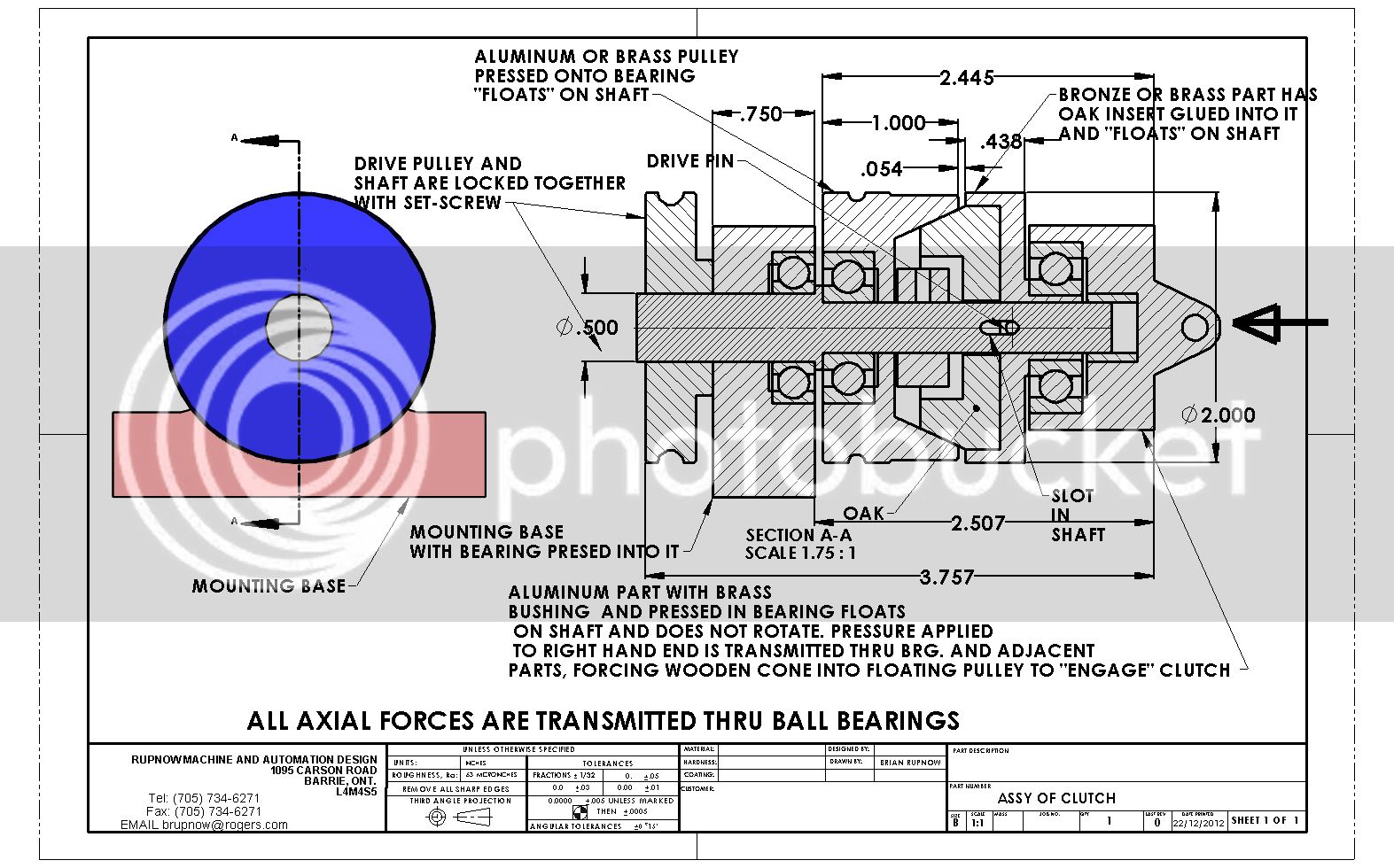
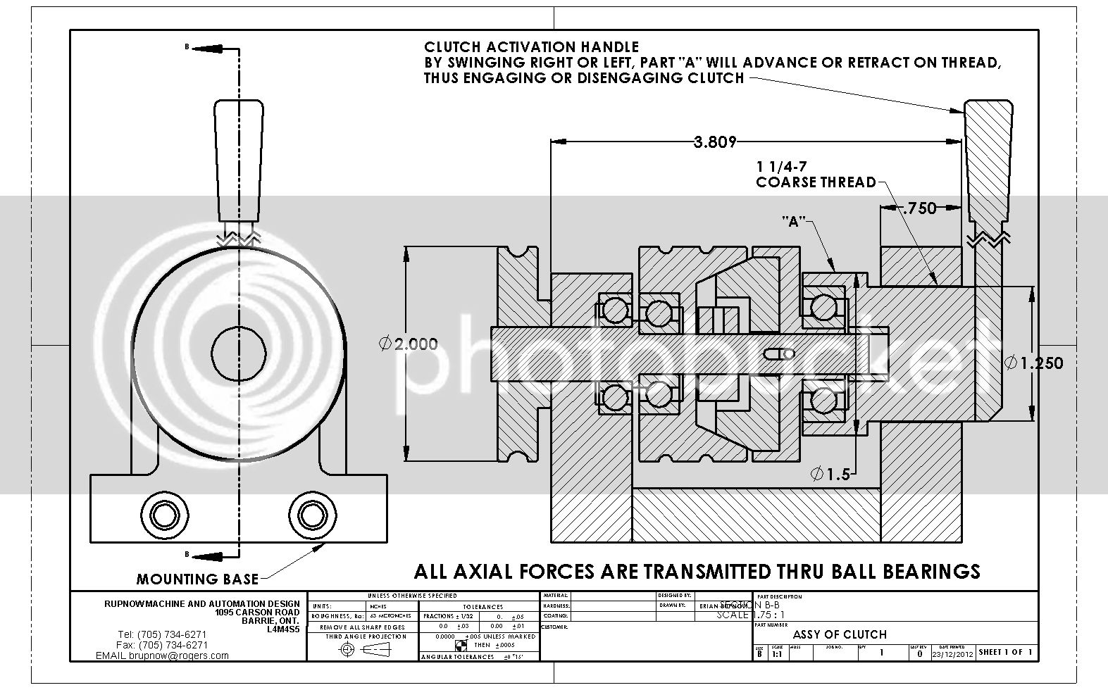
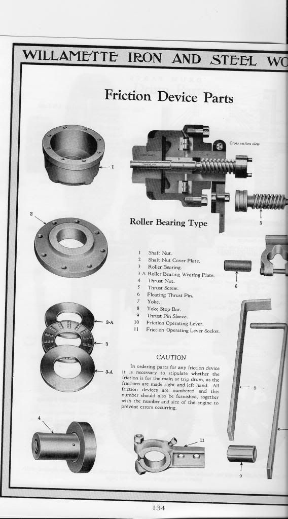
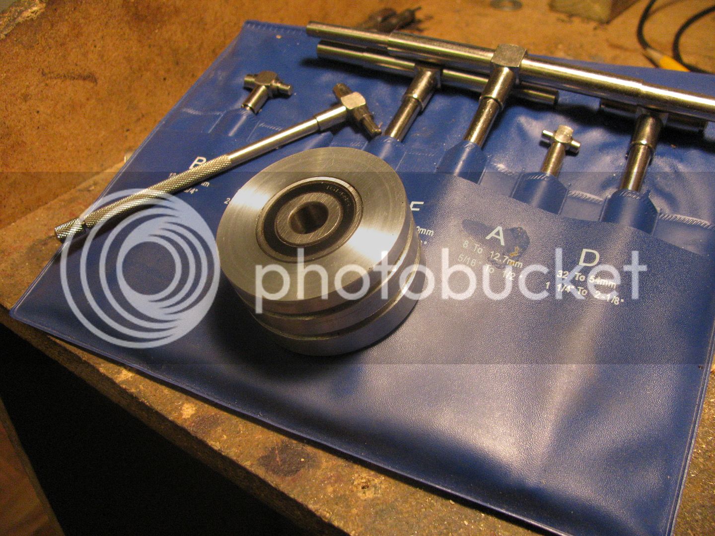
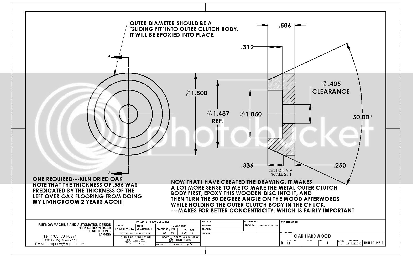
My brain never stops!!! Not all of my ideas are good ones, but I never run out of mechanical things to think about. Playing about with my model sawmill has got me thinking about simple mechanical clutches. Not something that tightens or loosens a drive belt, and not something that creates "drag" when disengaged. Rather some device that totally and completely disengages the driveshaft from whatever it is driving, and can be engaged softly like the clutch on an automobile, not with a sudden "grab and lurch". It would have to be simple, cheap, small, and a minimum of moving parts. I have many small, single race ball bearings from disassembling various "things" over the years, and they will take a lot of axial as well as radial pressure without failing. I was doodling on a piece of paper, and where the levers are in the sketch, think about a Destaco style clamp. Not the ones with the swinging lever, but the push/pull type. I see the friction material as being oak or maple, glued into a brass or aluminum housing. Not sure if I will build something like this or not, but it is intriguing!!!